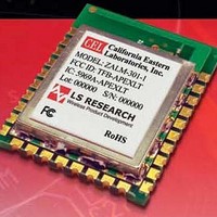
ZALM-301-1C-B CEL, ZALM-301-1C-B Datasheet - Page 4

ZALM-301-1C-B
Manufacturer Part Number
ZALM-301-1C-B
Description
Zigbee / 802.15.4 Modules & Development Tools Apex Lite 100mW Mod MMCX Connector
Manufacturer
CEL
Datasheet
1.ZALM-301-1C.pdf
(18 pages)
Specifications of ZALM-301-1C-B
Wireless Frequency
2400 MHz to 2483.5 MHz
Interface Type
SPI, UART
Operating Voltage
2.1 V 3.6 V
Output Power
100 mW
Antenna
MMCX
Operating Temperature Range
- 45 C to + 125 C
Lead Free Status / RoHS Status
Lead free / RoHS Compliant
APEX LT MODULE MICROPROCESSOR
APEX LT modules provide a connection to the Ember Serial API over the SPI allowing the application development to be
completed on a host microprocessor of your choice. In addition to the SPI signals, two additional signals (nHOST_INT and
nWAKE) provide a handshake mechanism. The module provides a slave device with all transactions initiated by the host.
Please consult the EM260 datasheet for details on the SPI Protocol including:
ANTENNA
APEX and APEX LT modules include an integrated PCB trace antenna.
An optional MMCX connector can be specified, enabling connection to
a 50-ohm external antenna of the user’s choice. See Ordering
Information.
The PCB antenna employs an F-Antenna topology that is compact and
supports an omni-directional radiation pattern.To maximize antenna efficiency, an adequate ground plane must be provided
on the host PCB. If positioned correctly, the ground plane on the host board under the module can contribute significantly
to antenna performance.
The position of the module on the host board and overall design of the product enclosure contribute to antenna perfor-
mance. Poor design effects radiation patterns and can result in reflection, diffraction, and/or scattering of the transmitted
signal. Measured radiation patterns of these modules are available from California Eastern Labs and can be used to
benchmark design performance.
Here are some design guidelines to help ensure antenna performance:
• Never place the ground plane or route copper traces directly underneath the antenna portion of the module.
• Never place the antenna close to metallic objects.
• In the overall design, ensure that wiring and other components are not placed near the antenna.
• Do not place the antenna in a metallic or metallized plastic enclosure.
• Keep plastic enclosures 1 cm or more from the antenna in any direction.
•
•
•
•
•
•
•
Physical Interface Configuration
SPI Transactions
SPI Protocol Timing Parameters & Waveforms
Data Formatting
SPI Commands & Responses
Handling Resets and Power Cycling
Transaction Examples
TOP VIEW
TOP VIEW
ZALM-300 Series
TOP VIEW


