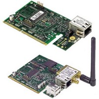
DC-ANT-E-24DT Digi International, DC-ANT-E-24DT Datasheet - Page 34

DC-ANT-E-24DT
Manufacturer Part Number
DC-ANT-E-24DT
Description
Wireless Accessories 30cm Extension Cord w/ RP-SMA Blkhd
Manufacturer
Digi International
Datasheet
1.DC-ANT-E-24DT.pdf
(86 pages)
Specifications of DC-ANT-E-24DT
Technology/ Type
Antenna
For Use With
Wi-EM
Lead Free Status / RoHS Status
Lead free / RoHS Compliant
- Current page: 34 of 86
- Download datasheet (8Mb)
GPIO Switch Bank 1 (SW1) and 2 (SW2)
3 4
D e v e l o p m e n t B o a r d L E D s
Development Board LEDs
D i g i C o n n e c t E M & W i - E M H a r d w a r e R e f e r e n c e
GPIO Switch Bank 1 and Switch Bank 2, labeled SW1 and SW2, are two sets of five slide
switches that set GPIO inputs to logic levels of high (switch to left) or low (switch to
right).
If the GPIO port is configured as an output, then the switch should always be to the left. If
there is an external device connected to P3, the switch should always be set to the left.
Each GPIO port can be used independently.
Notes:
The development board contains 21 LEDs labeled CR1 through CR21. The following table
lists and describes the LEDs.
Board
Label
CR1
CR2
CR3
These switches do not determine whether the GPIO is an input or output. That
is determined by the module software.
If GPIO is set to an output by software, switches must be set to the left (high).
These switches are used in conjunction with SW3 and SW4.
Description
TXD-2
RXD-2
CTS
LED Descriptions
Flickering
Green
Flickering
Green
Yellow
Green
Off
Color or State
Serial activity
Inactive
Serial activity
Inactive
Active
Inactive
Not connected or signal
not being driven
Indication
Related parts for DC-ANT-E-24DT
Image
Part Number
Description
Manufacturer
Datasheet
Request
R

Part Number:
Description:
CORD EXT 30CM W/RP-SMA CONN (1)
Manufacturer:
Digi International
Datasheet:

Part Number:
Description:
CORD EXT 30CM W/RP-SMA CONN (10)
Manufacturer:
Digi International
Datasheet:

Part Number:
Description:
CORD EXT 30CM W/RP-SMA CONN (10)
Manufacturer:
Digi International
Datasheet:

Part Number:
Description:
CORD EXT 30CM W/RP-SMA CONN (25)
Manufacturer:
Digi International
Datasheet:

Part Number:
Description:
CORD EXT 30CM W/RP-SMA CONN (25)
Manufacturer:
Digi International
Datasheet:

Part Number:
Description:
CORD EXT 30CM W/RP-SMA CONN (50)
Manufacturer:
Digi International
Datasheet:

Part Number:
Description:
CORD EXT 30CM W/RP-SMA CONN (50)
Manufacturer:
Digi International
Datasheet:

Part Number:
Description:
ANTENNA 2.4GHZ DIPOLE 2DBI 1PC
Manufacturer:
Digi International
Datasheet:

Part Number:
Description:
ANTENNA 2.4GHZ DESKTOP 2DBI 1PC
Manufacturer:
Digi International
Datasheet:

Part Number:
Description:
ANTENNA 2.4GHZ DIPOLE 2DBI 10PC
Manufacturer:
Digi International
Datasheet:

Part Number:
Description:
DIGI CONNECT 4MB FLASH 8MB RAM
Manufacturer:
Digi International
Datasheet:

Part Number:
Description:
ENCRYPTION ENGINE 10/100 INT
Manufacturer:
Digi International
Datasheet:

Part Number:
Description:
ME 9210 8MB SDRAM 4MB FLASH SGL
Manufacturer:
Digi International
Datasheet:

Part Number:
Description:
ME 8MB SDRAM 2MB FLASH SINGLE
Manufacturer:
Digi International
Datasheet:


