DLP-RF2-PROTO DLP Design Inc, DLP-RF2-PROTO Datasheet - Page 2
DLP-RF2-PROTO
Manufacturer Part Number
DLP-RF2-PROTO
Description
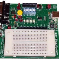
Zigbee / 802.15.4 Modules & Development Tools TTL SERIAL INTERFACE PROTO BOARD
Manufacturer
DLP Design Inc
Datasheet
1.DLP-RF2-PROTO.pdf
(5 pages)
Specifications of DLP-RF2-PROTO
Wireless Frequency
2.4 GHz
Interface Type
RS-232, USB
Operating Voltage
3 V
For Use With/related Products
MC9S08GT60
Lead Free Status / RoHS Status
Lead free / RoHS Compliant


USB INTERFACE
A USB interface is provided in the event that the user wants to test out a system design using the
programming resources of a host PC. Serial host software used to communicate with the DLP-RF2 can
be developed and tested using standard PC development tools (compilers/debuggers/etc.) that will
ultimately execute in a user-supplied microcontroller/DSP/etc. If a system requires permanent connection
to a host computer then the DLP-RF1 should be used instead of the DLP-RF2 and DLP-RF2PROTO
combination as the DLP-RF1 has its own USB interface for host communications.
The USB interface on the DLP-RF2PROTO, in conjunction with the DLP Design RFTestAp software, can
be used to easily set/change the communications parameters of the DLP-RF2 transceiver. The
RFTestAp software and its Visual C++ source code can be downloaded from the DLP Design website
upon purchase of the DLP-RF2PROTO.
The communications interface between the FT232BM USB IC and the DLP-RF2 transceiver is bi-direction
3-volt serial data over a 2-wire (TX/RX) connection. Only selected baud rates (2400, 4800, 9600, 14400,
19200, 38400, 128000, 250000 baud) can be used to communicate with the DLP-RF2, with the default
being 9600 baud. The baud rate is set by the host application at run time.
Operational power for the DLP-RF2PROTO and DLP-RF2 can be taken from the host PC via the USB
interface. All that is required is a user-supplied, 6-foot USB cable and to set the power select jumper
(JP5) correctly. The power select jumper settings are covered in the next section.
If using Windows XP (SP1 or more recent) or Linux (Kernel 2.4.0 and greater) the VCP drivers for the
USB port on the host computer should already be loaded and ready for use. Otherwise, VCP drivers for
the operating system in use can be downloaded from www.dlpdesign.com. To load the drivers, simply
connect the DLP-RF2PROTO to the USB port of the host computer. A wizard will appear requesting the
location of the drivers. Once the wizard has finished, Device Manager should be opened to verify the
presence of a new COM port in the “Ports COM & LPT” section.
POWER-SELECTION JUMPERS
Jumper JP5 allows a power source to be selected as outlined in Table 1.
SWITCHES AND LED’S
All available I/O lines from the DLP-RF2 are made available on connector CN2. The switches and LED’s
on the DLP-RF2PROTO board are used primarily for digital I/O (A6, B6-B0) indication and control. If a
data line is set to be an input to the microcontroller with the internal pull-ups disabled, the 1M Ohm pull-
down resistors will keep the line from oscillating. If set to an input with the internal pull-up resistors
enabled, the line will be held high as the internal pull-ups can easily overcome the 1M pull-down resistors.
The 8 switches at position SW1 can be used to simulate inputs from the user interface. Care should be
taken to prevent turning “On” a switch for an I/O line that is set to output and high as this will short the line
to ground and possibly damage the microcontroller on the DLP-RF2.
Rev 1.0 (March 2005)
Position
1-2
3-4
5-6
External 4-15VDC Power Supply
Battery clips for 9-volt battery or 6-
USB Port Power
Power Source Selected
volt batter pack
Table 1
2
DLP-RF2PROTO DLP Design, Inc.
Related parts for DLP-RF2-PROTO
Image
Part Number
Description
Manufacturer
Datasheet
Request
R

Part Number:
Description:
Zigbee / 802.15.4 Modules & Development Tools USE 626-DLP-RF2-Z
Manufacturer:
DLP Design Inc
Datasheet:

Part Number:
Description:
Zigbee / 802.15.4 Modules & Development Tools LATCHING RELAY BOARD FOR RF2 MODULE
Manufacturer:
DLP Design Inc
Datasheet:

Part Number:
Description:
Industrial Humidity Sensors TEMP AND HUMIDITY SENSOR FOR RF2 MOD.
Manufacturer:
DLP Design Inc
Datasheet:
Part Number:
Description:
Zigbee / 802.15.4 Modules & Development Tools TTL SERIAL INTERFACE MODULE
Manufacturer:
DLP Design Inc
Datasheet:
Part Number:
Description:
Zigbee / 802.15.4 Modules & Development Tools TTL SERIAL INTERFACE MODULE
Manufacturer:
DLP Design Inc
Datasheet:

Part Number:
Description:
MODULE DATA-ACQUISITION 8-CH
Manufacturer:
DLP Design Inc
Datasheet:

Part Number:
Description:
MODULE DATA-ACQUISITION 20-CH
Manufacturer:
DLP Design Inc
Datasheet:

Part Number:
Description:
RFID READER/WRITER SNGL-CH OEM
Manufacturer:
DLP Design Inc
Datasheet:

Part Number:
Description:
MODULE USB-MCU FT245RL W/16F877A
Manufacturer:
DLP Design Inc
Datasheet:

Part Number:
Description:
MODULE USB-TO-FPGA TRAINING TOOL
Manufacturer:
DLP Design Inc
Datasheet:

Part Number:
Description:
MODULE USB-MCU FT232R W/18F2410
Manufacturer:
DLP Design Inc
Datasheet:

Part Number:
Description:
MODULE USB-MCU FT245RL W/SX48
Manufacturer:
DLP Design Inc
Datasheet:

Part Number:
Description:
MODULE USB-MCU FT2232D W/16F877A
Manufacturer:
DLP Design Inc
Datasheet:

Part Number:
Description:
MODULE USB-TO-FPGA SPARTAN3
Manufacturer:
DLP Design Inc
Datasheet:

Part Number:
Description:
MOD USB-MCU FT245RL W/18LF8722
Manufacturer:
DLP Design Inc
Datasheet: