70MT120KPBF Vishay, 70MT120KPBF Datasheet - Page 2
70MT120KPBF
Manufacturer Part Number
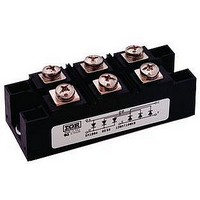
70MT120KPBF
Description
Bridge Rectifiers 1200 Volt 70 Amp
Manufacturer
Vishay
Specifications of 70MT120KPBF
Package / Case
INT-A-PAK
Product
Three Phase Bridge
Peak Reverse Voltage
1200 V
Max Surge Current
500 A
Forward Voltage Drop
1.55 V
Maximum Reverse Leakage Current
10000 uA
Maximum Operating Temperature
+ 150 C
Length
94 mm
Width
35 mm
Height
39 mm
Mounting Style
Screw
Minimum Operating Temperature
- 40 C
Repetitive Reverse Voltage Vrrm Max
1.2kV
Leaded Process Compatible
Yes
Lead Free Status / RoHS Status
Lead free / RoHS Compliant


Thermal and Mechanical Specifications
60-70MT..KB Series
Bulletin I27500 rev. A 05/03
2
Forward Conduction
ELECTRICAL SPECIFICATIONS
Voltage Ratings
T
T
R
R
T
wt
I
I
I
I
V
V
r
r
V
V
Type number
60-70MT..KB
O
FSM
2
2
f1
f2
J
stg
thJC
thCS
t
F(TO)1
F(TO)2
FM
INS
t
Parameter
Parameter
Max. junction operating temperature range
Max. storage temperature range
Max. thermal resistance, junction to case
Max. thermal resistance, case to heatsink
Mounting torque ± 10%
Approximate weight
Maximum DC output current
@ Case temperature
Maximum peak, one-cycle forward,
non-repetitive surge current
Maximum I
Maximum I
Low level value of threshold voltage
High level value of threshold voltage
Low level value of forward slope resistance
High level value of forward slope resistance
Maximum forward voltage drop
RMS isolation voltage
2
2
Voltage
t for fusing
t for fusing
Code
100
120
140
160
80
V
to heatsink
to terminal
RRM
peak reverse voltage
, maximum repetitive
1000
1200
1400
1600
800
V
60MT.KB 70MT.KB Units Conditions
60MT.KC 70MT.KC Units Conditions
60 (75)
85 (61)
4000
8700
0.37
2.22
0.40
2.42
0.85
1.07
8.04
7.08
1.75
420
440
350
370
870
790
610
560
-40 to 150
-40 to 150
4 to 6
3 to 4
0.03
176
70 (90)
85 (57)
11300
1050
4000
1150
0.29
1.75
0.34
2.01
0.86
1.08
7.35
6.53
1.55
480
500
400
420
800
730
repetitive peak rev. voltage
K/W
K/W
A
Nm
m
A
°C
°C
°C
A
A
2
V
V
V
g
2
V
s
s
RSM
DC operation per module
DC operation per junction
120° Rect condunction angle per module
120° Rect condunction angle per junction
Per module
Mounting surface smooth, flat and greased
t = 8.3ms
A mounting compound is recommended and
the
period of 3 hours to allow for the spread of the
compound. Lubricated threads.
120° Rect conduction angle
t = 10ms
t = 8.3ms
t = 10ms
t = 8.3ms
t = 10ms
t = 10ms
t = 8.3ms
t = 0.1 to 10ms, no voltage reapplied
(16.7% x x I
(I >
(16.7% x x I
(I >
I
T
f = 50Hz, t = 1s
pk
J
, maximum non-
= 100A, T
= 25°C, all terminal shorted
1100
1300
1500
1700
900
x I
x I
V
torque should be rechecked after a
F(AV)
F(AV)
J
No voltage
reapplied
100% V
reapplied
No voltage
reapplied
100% V
reapplied
), @ T
), @ T
F(AV)
F(AV)
= 25°C, t
< I < x I
< I < x I
J
J
RRM
RRM
max.
max.
p
= 400µs single junction
Initial T
F(AV)
F(AV)
www.irf.com
I
@ T
), @ T
), @ T
RRM
J
mA
= T
10
J
max.
max.
J
J
J
max.
max.
max.
Related parts for 70MT120KPBF
Image
Part Number
Description
Manufacturer
Datasheet
Request
R

Part Number:
Description:
357-036-542-201 CARDEDGE 36POS DL .156 BLK LOPRO
Manufacturer:
Vishay
Datasheet:
Part Number:
Description:
357-036-542-201 CARDEDGE 36POS DL .156 BLK LOPRO
Manufacturer:
Vishay
Datasheet:
Part Number:
Description:
357-036-542-201 CARDEDGE 36POS DL .156 BLK LOPRO
Manufacturer:
Vishay
Datasheet:
Part Number:
Description:
357-036-542-201 CARDEDGE 36POS DL .156 BLK LOPRO
Manufacturer:
Vishay
Datasheet:
Part Number:
Description:
357-036-542-201 CARDEDGE 36POS DL .156 BLK LOPRO
Manufacturer:
Vishay
Datasheet:
Part Number:
Description:
357-036-542-201 CARDEDGE 36POS DL .156 BLK LOPRO
Manufacturer:
Vishay
Datasheet:
Part Number:
Description:
357-036-542-201 CARDEDGE 36POS DL .156 BLK LOPRO
Manufacturer:
Vishay
Datasheet:
Part Number:
Description:
357-036-542-201 CARDEDGE 36POS DL .156 BLK LOPRO
Manufacturer:
Vishay
Datasheet:
Part Number:
Description:
357-036-542-201 CARDEDGE 36POS DL .156 BLK LOPRO
Manufacturer:
Vishay
Datasheet:
Part Number:
Description:
357-036-542-201 CARDEDGE 36POS DL .156 BLK LOPRO
Manufacturer:
Vishay
Datasheet:
Part Number:
Description:
357-036-542-201 CARDEDGE 36POS DL .156 BLK LOPRO
Manufacturer:
Vishay
Datasheet:
Part Number:
Description:
357-036-542-201 CARDEDGE 36POS DL .156 BLK LOPRO
Manufacturer:
Vishay
Datasheet:
Part Number:
Description:
357-036-542-201 CARDEDGE 36POS DL .156 BLK LOPRO
Manufacturer:
Vishay
Datasheet:
Part Number:
Description:
357-036-542-201 CARDEDGE 36POS DL .156 BLK LOPRO
Manufacturer:
Vishay
Datasheet:
Part Number:
Description:
357-036-542-201 CARDEDGE 36POS DL .156 BLK LOPRO
Manufacturer:
Vishay
Datasheet: