1N5342BRLG ON Semiconductor, 1N5342BRLG Datasheet - Page 6
1N5342BRLG
Manufacturer Part Number
1N5342BRLG
Description
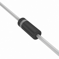
DIODE ZENER 6.8V 5W AXIAL
Manufacturer
ON Semiconductor
Series
Surmetic™r
Type
Voltage Regulatorr
Datasheet
1.1N5349BRLG.pdf
(7 pages)
Specifications of 1N5342BRLG
Voltage - Zener (nom) (vz)
6.8V
Voltage - Forward (vf) (max) @ If
1.2V @ 1A
Current - Reverse Leakage @ Vr
10µA @ 5.2V
Tolerance
±5%
Power - Max
5W
Impedance (max) (zzt)
1 Ohm
Mounting Type
Through Hole
Package / Case
Axial
Operating Temperature
-65°C ~ 200°C
Zener Voltage
6.8 V
Voltage Tolerance
5 %
Zener Current
700 mA
Power Dissipation
5 W
Maximum Reverse Leakage Current
10 uA
Maximum Zener Impedance
1 Ohms
Maximum Operating Temperature
+ 200 C
Mounting Style
SMD/SMT
Forward Voltage Drop
1.2 V
Minimum Operating Temperature
- 65 C
Voltage Regulation Accuracy
150 mV
Zener Voltage Vz Typ
6.8V
Power Dissipation Pd
5W
Operating Temperature Range
-65°C To +200°C
Diode Case Style
017AA
No. Of Pins
2
Diode Type
Zener
Peak Reflow Compatible (260 C)
Yes
Rohs Compliant
Yes
Configuration
Single
Package Type
Case 017AA-01
Zener Voltage (typ)
6.8V
Zener Test Current
175mA
Knee Impedance
1Ohm
Operating Temperature Classification
Military
Rev Curr
10uA
Mounting
Through Hole
Pin Count
2
Operating Temp Range
-65C to 200C
Filter Terminals
Axial Leaded
Lead Free Status / RoHS Status
Lead free / RoHS Compliant
Other names
1N5342BRLGOSTR
Available stocks
Company
Part Number
Manufacturer
Quantity
Price
Company:

Part Number:
1N5342BRLG
Manufacturer:
ON
Quantity:
4 000
Company:
Part Number:
1N5342BRLG
Manufacturer:
ON
Quantity:
30 000
Part Number:
1N5342BRLG
Manufacturer:
ON/安森美
Quantity:
20 000
Part Number:
1N5342BRLG 6.8V
Manufacturer:
VISHAY/威世
Quantity:
20 000


diode is temperature dependent, it is necessary to determine
junction temperature under any set of operating conditions
in order to calculate its value. The following procedure is
recommended:
q
power dissipation.
DT
temperature and may be found from Figure 4 for a train of
power pulses or from Figure 1 for dc power.
LA
Since the actual voltage available from a given Zener
Lead Temperature, T
Junction Temperature, T
JL
is the lead‐to‐ambient thermal resistance and P
is the increase in junction temperature above the lead
T
T
L
DT
L
J
= q
, should be determined from:
= T
JL
J
LA
, may be found from:
= q
L
P
+ DT
JL
D
+ T
100
P
0.1
10
JL
D
1
80
A
Figure 9. Zener Voltage versus Zener Current
100
APPLICATION NOTE
120
D
1N5333B Series
http://onsemi.com
V
is the
Z
V
= 82 thru 200 Volts
Z
, ZENER VOLTAGE (VOLTS)
140
6
of P
Changes in voltage, V
q
from Figures 2 and 3.
vary with time and may also be affected significantly by the
zener resistance. For best regulation, keep current
excursions as low as possible.
capability. Surge limitations are given in Figure 5. They are
lower than would be expected by considering only junction
temperature, as current crowding effects cause temperatures
to be extremely high in small spots resulting in device
degradation should the limits of Figure 5 be exceeded.
160
VZ
For worst‐case design, using expected limits of I
Under high power‐pulse operation, the Zener voltage will
Data of Figure 4 should not be used to compute surge
, the Zener voltage temperature coefficient, is found
D
and the extremes of T
180
200
Z
DV = q
, can then be found from:
220
VZ
J
DT
(DT
J
J
) may be estimated.
Z
, limits
Related parts for 1N5342BRLG
Image
Part Number
Description
Manufacturer
Datasheet
Request
R

Part Number:
Description:
DIODE ZENER 6.8V 5W AXIAL
Manufacturer:
ON Semiconductor
Datasheet:


Part Number:
Description:
ON Semiconductor [VOLTAGE REGULATOR]
Manufacturer:
ON Semiconductor
Datasheet:
Part Number:
Description:
357-036-542-201 CARDEDGE 36POS DL .156 BLK LOPRO
Manufacturer:
ON Semiconductor
Datasheet:
Part Number:
Description:
357-036-542-201 CARDEDGE 36POS DL .156 BLK LOPRO
Manufacturer:
ON Semiconductor
Datasheet:
Part Number:
Description:
357-036-542-201 CARDEDGE 36POS DL .156 BLK LOPRO
Manufacturer:
ON Semiconductor
Datasheet:
Part Number:
Description:
357-036-542-201 CARDEDGE 36POS DL .156 BLK LOPRO
Manufacturer:
ON Semiconductor
Datasheet:
Part Number:
Description:
357-036-542-201 CARDEDGE 36POS DL .156 BLK LOPRO
Manufacturer:
ON Semiconductor
Datasheet:
Part Number:
Description:
357-036-542-201 CARDEDGE 36POS DL .156 BLK LOPRO
Manufacturer:
ON Semiconductor
Datasheet:
Part Number:
Description:
357-036-542-201 CARDEDGE 36POS DL .156 BLK LOPRO
Manufacturer:
ON Semiconductor
Datasheet:
Part Number:
Description:
357-036-542-201 CARDEDGE 36POS DL .156 BLK LOPRO
Manufacturer:
ON Semiconductor
Datasheet:
Part Number:
Description:
357-036-542-201 CARDEDGE 36POS DL .156 BLK LOPRO
Manufacturer:
ON Semiconductor
Datasheet:
Part Number:
Description:
357-036-542-201 CARDEDGE 36POS DL .156 BLK LOPRO
Manufacturer:
ON Semiconductor
Datasheet:
Part Number:
Description:
Manufacturer:
ON Semiconductor
Datasheet: