583649-6 TE Connectivity, 583649-6 Datasheet - Page 93
583649-6
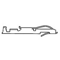
Manufacturer Part Number
583649-6
Description
TW LF CONTACT LP OF 583649-3
Manufacturer
TE Connectivity
Type
Bifurcated Contactr
Datasheet
1.583649-6.pdf
(96 pages)
Specifications of 583649-6
Number Of Contacts
1POS
Body Orientation
Straight
Contact Plating
Gold Over Nickel
Contact Material
Phosphor Bronze
Termination Method
Crimp
Mounting Style
Cable
Product Height (mm)
3.35mm
Operating Temp Range
-55C to 105C
Pitch (mm)
Not Requiredmm
Current Rating (max)
5A
Contact Resistance Max
10
Rohs Compliant
NO
Product Type
Contact
Termination Method To Wire/cable
Crimp
Wire Insulation Diameter (mm [in])
1.14 – 2.41 [0.045 – 0.095]
Color Code
Violet
Contact Retention In Housing
Crimp Snap-In
Solder Tail Contact Plating
Nickel (30)
Centerline (mm [in])
3.18 [0.125], 3.96 [0.156]
Wire Range (mm [awg])
0.30-0.90² [22-18]
Contact Configuration
Bifurcated
Contact Plating, Mating Area, Material
Gold (30)
Contact Base Material
Phosphor Bronze
Rohs/elv Compliance
Not ELV/RoHS compliant
Lead Free Solder Processes
Not relevant for lead free process
Contact Packaging Method
Loose Piece
Lead Free Status / RoHS Status
Not Compliant


*At least two (2) contact combs required per housing.
Note: Other sizes can be made available, consult Tyco Electronics.
Catalog 1654080
Issued 7-03
www.tycoelectronics.com
ACTION PIN Contacts with Wiping Feature,
.125 [3.18] Centerline
Material and Finish:
Copper alloy 725, plated .000015
[0.00038] gold per MIL-G-45204 in
contact area; .000001 [0.00003] min.
gold flash per MIL-G-45204 on post
with entire contact underplated .000050
[0.00127] nickel per QQ-N-290
Contact Combs
Per Comb*
Number of
[37.85]
Contacts
1.490
56
Post Area
[19.05]
[18.80]
.750
.740
[3.18]
.125
Dimensions are in inches and
millimeters unless otherwise
specified. Values in brackets
are metric equivalents.
(Comb)
A
Dimension
174.63
6.875
A
Related Product Data:
Performance Specifications—
page 83
ACTION PIN Contact Description
and Application Specification—
page 94
Tooling—page 95
Technical Documents:
(pages 186, 187):
Instruction Sheet 408-2665
Card Edge Connectors
(Solder Type, Board-to-Board)
Linear ZIF Connectors, .125 x .125 [3.18 x 3.18] Centerline
Contact Area
[1.14]
.045
[0.64]
.025
[15.24]
.600
Sq.
Ref.
Dimensions are shown for
reference purposes only.
Specifications subject
to change.
1-119950-2
Number
Part
at Assembly
Prenotched
for Breakoff
[3.05]
.120
Recommended PC Board Hole Layout and Edge Pattern,
.125 [3.18] Centerline
Mother Board Hole Layout
*For ACTION PIN post hole diameter, see page 94.
Daughter Board Edge Pattern
Connector
Connector
Bell-Crank
Bell-Crank
Dia.
Lever
Lever
Style
Style
Min.
B
USA: 1-800-522-6752
Canada: 1-905-470-4425
Mexico: 01-800-733-8926
C. America: 52-55-5-729-0425
B
Max.
A
[2.79]
.110
.125
3.18
.125
3.18
C L
C
Entry
Style
L
Side
[3.18]
Top
Top
.125
Typ.
[3.18 (No. of Pos. –1) +5.59]
[5.08]
.200
.125 (No. of Pos. –1) +.220
.125
3.18
.125
3.18
Min.
A
South America: 55-11-3611-1514
Hong Kong: 852-2735-1628
Japan: 81-44-844-8013
UK: 44-141-810-8967
Dimensions
19.68
.240
6.10
.240
6.10
.775
A
[1.19]
(Solder Post Only)*
.047
(Continued)
[1.78]
Dimensions
1.250
31.75
.090
.218
5.54
Dia. Typ.
B
Typ.
C
15.24
.320
8.13
.600
.187
4.75
.187
4.75
—
B
C
93
Related parts for 583649-6
Image
Part Number
Description
Manufacturer
Datasheet
Request
R

Part Number:
Description:
CONT TWIN LEAF
Manufacturer:
TE Connectivity
Datasheet:
Part Number:
Description:
CONT.CRP.SNAP TW.LF.STRIP
Manufacturer:
TE Connectivity
Datasheet:

Part Number:
Description:
CONT.CRP.SNAP TW.LF.STRIP
Manufacturer:
TE Connectivity
Datasheet:

Part Number:
Description:
High Speed / Modular Connectors 30P HEADER ASSY
Manufacturer:
TE Connectivity
Datasheet:

Part Number:
Description:
High Speed / Modular Connectors REC 6X005P R/A LT B-PLANE HS3
Manufacturer:
TE Connectivity
Datasheet:

Part Number:
Description:
High Speed / Modular Connectors 2MM HM RCPT 50P R/A AU
Manufacturer:
TE Connectivity
Datasheet:

Part Number:
Description:
High Speed / Modular Connectors 2MM HM RCPT 50P R/A AU
Manufacturer:
TE Connectivity
Datasheet:


Part Number:
Description:
Manufacturer:
TE Connectivity
Datasheet:


Part Number:
Description:
Manufacturer:
TE Connectivity
Datasheet:

Part Number:
Description:
Manufacturer:
TE Connectivity
Datasheet:

Part Number:
Description:
Manufacturer:
TE Connectivity
Datasheet: