MS27473E14B35S Amphenol, MS27473E14B35S Datasheet - Page 15
MS27473E14B35S
Manufacturer Part Number
MS27473E14B35S
Description
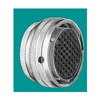
Circular MIL / Spec Connectors 37P 14 SIZE STRAIGHT PLUG SKT
Manufacturer
Amphenol
Type
MIL-DTL38999 Circulrr
Series
JT Seriesr
Datasheet
1.MS27473T22B32P.pdf
(42 pages)
Specifications of MS27473E14B35S
Contact Gender
SKT
Gender
PL
Number Of Contacts
37POS
Shell Size / Insert Arrangement
14-35
Mounting Style
Cable
Termination Method
Crimp
Shell Plating
Olive Drab Cadmium
Contact Plating
Gold
Body Orientation
Straight
Strain Relief
No
Contact Classification
37Signal
Operating Temp Range
-65C to 200C
Product Diameter (mm)
28.98mm
Product Length (mm)
23.82mm
Mil Type
MIL-DTL-38999 II
Product Type
Connectors
Contact Style
Socket (Female)
Shell Style
Plug
Shell Size
14
Insert Arrangement
14-35
Mating Style
Receptacle
Termination Style
Crimp
Contact Type
Socket
Current Rating
5 A
Voltage Rating
500 V
Body Material
Aluminum Alloy
Mounting Angle
Straight
Lead Free Status / RoHS Status
Compliant


48
Contact Amphenol Aerospace for more information at 800-678-0141 • www.amphenol-aerospace.com
Amphenol
Step 6.
Alternate Keying Position
“A” designates Alternate keying
connector assembly. Other basic
alternate keys are “B”, “C” and “D”.
No letter required for normal rotation
(no rotation) position.
A plug with a given rotation letter will
mate with a receptacle with the same
rotation letter. The AB angle for a
given connector is the same whether
it contains pins or sockets. Only the
master key/keyway rotates in the
shell, and the minor keys are fixed.
AB angles shown are viewed from the
front face of the connec tor, a recep-
tacle is shown below. The angles for
the plug are exactly the same except
the direction of rotation is opposite of
that shown for the receptacle.
The “N” designation is not referenced in
part number, it is omitted.
Step 7.
Relief Option or Finish
Variation Suffix
Strain Relief Options: “SR” designates a strain
relief clamp. Strain reliefs are available only on
Service Class “A”, “C” and “RE” (see step 3.
Service Class)
Finish Variation Suffix: See finish variations
available in table to your right.
Connector Type
Connector
Type
1.
1.
Select an
Select a Strain
Shell Style
Shell Style
Aerospace
2.
2.
Service Class
Service Class
3.
3.
Insert Arrg.
Insert Arrg.
Shell
Shell Size
4.
4.
Size-
Contact Type
Contact Type
5.
5.
MIL-DTL-38999, Series I LJT
MIL-DTL-38999, Series II JT
How to Order (Commercial)
AB
AB
5˚ LJT REF
10˚ JT REF
Alternate
Position
RELATIVE POSSIBLE POSITION
OF ROTATED MASTER KEYWAY
RELATIVE POSSIBLE POSITION
OF ROTATED MASTER KEYWAY
(front face of receptacle shown)
Alternate
(front face of receptacle shown)
Position
6.
6.
A
B
B
Variations
A
A
NORMAL
NORMAL
Special
Variations
7.
7.
Special
( )
D
D
C
C
ROTATION
LETTERS
ROTATION
LETTERS
Cadmium plated nickel base
175° C
Olive drab cadmium plate
nickel base 175° C
Electroless nickel 200° C
Electroless nickel, space
compatible 200° C
Anodic coating (Alumilite)
200° C
Chromate treated (Iridite
14-2) 125° C
Passivated steel 200° C
Nickel-PTFE 175° C
Finish
Shell Size
Shell Size
11
13
15
17
19
21
23
25
10
12
14
16
18
20
22
24
9
8
AB ANGLE OF ROTATION (Degrees)
AB ANGLE OF ROTATION (Degrees)
JT
LJT
Finish Data
Key/Keyway Rotation
Military
Key/Keyway Rotation
Normal
Normal
100°
100°
100°
100°
100°
100°
100°
100°
100°
95°
95°
95°
95°
95°
95°
95°
95°
95°
C
A
B
F
E
77°
81°
75°
74°
77°
77°
77°
80°
80°
82°
86°
80°
79°
82°
82°
82°
85°
85°
A
A
Finish
Suffix
(014)
(023)
(453)
(005)
(011)
(038)
-
72°
68°
66°
70°
70°
70°
74°
74°
67°
63°
61°
65°
65°
65°
69°
69°
B
B
-
-
128°
132°
134°
130°
130°
130°
126°
126°
123°
127°
129°
125°
125°
125°
121°
121°
Finish Plus
“SR” Suffix
C
-
C
-
(386)
(424)
(467)
(300)
(344)
(SR)
-
118°
114°
120°
121°
118°
118°
118°
115°
115°
113°
109°
115°
116°
113°
113°
113°
110°
110°
D
D
Related parts for MS27473E14B35S
Image
Part Number
Description
Manufacturer
Datasheet
Request
R

Part Number:
Description:
Circular MIL / Spec Connectors STRAIGHT PLUG SIZE 22 35 PIN NICKEL PLT
Manufacturer:
Amphenol
Datasheet:

Part Number:
Description:
Cable Specification: PU CABLE, UL20549 24AWG*8C+AD,OD= 6.0mm
Manufacturer:
Amphenol
Part Number:
Description:
BEN44-104-10005-2 5 WAY 44 RECEPTACLE INSULATOR
Manufacturer:
Amphenol