GA200SA60UP Vishay, GA200SA60UP Datasheet - Page 2
GA200SA60UP
Manufacturer Part Number
GA200SA60UP
Description
IGBT Transistors N-Ch 600 Volt 100A
Manufacturer
Vishay
Datasheet
1.GA200SA60UP.pdf
(7 pages)
Specifications of GA200SA60UP
Configuration
Single
Collector- Emitter Voltage Vceo Max
600 V
Maximum Gate Emitter Voltage
+/- 20 V
Maximum Operating Temperature
+ 150 C
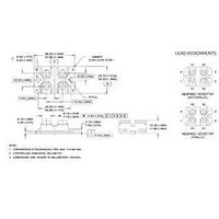
Package / Case
SOT-227-4
Continuous Collector Current Ic Max
200 A
Minimum Operating Temperature
- 55 C
Mounting Style
SMD/SMT
Dc Collector Current
200A
Collector Emitter Voltage Vces
600V
Power Dissipation Pd
500W
Collector Emitter Voltage V(br)ceo
600V
Operating Temperature Range
-55°C To +150°C
No. Of Pins
4
Lead Free Status / RoHS Status
Lead free / RoHS Compliant
Lead Free Status / RoHS Status
Lead free / RoHS Compliant, Lead free / RoHS Compliant
Available stocks
Company
Part Number
Manufacturer
Quantity
Price

Part Number:
GA200SA60UP
Quantity:
63
Company:
Part Number:
GA200SA60UPBF
Manufacturer:
AVX
Quantity:
25 000


GA200SA60UP
Vishay Semiconductors
www.vishay.com
2
ELECTRICAL SPECIFICATIONS (T
PARAMETER
Collector to emitter breakdown voltage
Emitter to collector breakdown voltage
Temperature coeff. of breakdown
Collector to emitter saturation voltage
Gate threshold voltage
Temperature coeff. of threshold voltage
Forward transconductance
Zero gate voltage collector current
Gate to emitter leakage current
SWITCHING CHARACTERISTICS (T
PARAMETER
Total gate charge (turn-on)
Gate-emitter charge (turn-on)
Gate-collector charge (turn-on)
Turn-on delay time
Rise time
Turn-off delay time
Fall time
Turn-on switching loss
Turn-off switching loss
Total switching loss
Turn-on delay time
Rise time
Turn-off delay time
Fall time
Total switching loss
Internal emitter inductance
Input capacitance
Output capacitance
Reverse transfer capacitance
DiodesAmericas@vishay.com, DiodesAsia@vishay.com,
For technical questions within your region, please contact one of the following:
V
Insulated Gate Bipolar Transistor
V
SYMBOL
SYMBOL
V
V
(BR)CES
(Ultrafast Speed IGBT), 100 A
V
V
GE(th)
(BR)CES
(BR)ECS
t
t
t
t
C
I
I
C
C
J
CE(on)
Q
Q
E
GE(th)
d(on)
d(off)
E
d(on)
d(off)
Q
E
E
g
CES
GES
L
t
t
t
t
oes
res
J
on
off
ies
ge
gc
ts
ts
= 25 °C unless otherwise specified)
fe
r
f
r
f
E
g
/T
= 25 °C unless otherwise specified)
/T
J
J
I
V
V
T
I
V
V
R
Energy losses include “tail”
See fig. 9, 10, 14
T
I
V
Energy losses include “tail”
See fig. 10, 11, 14
Measured 5 mm from package
V
V
f = 1.0 MHz; See fig. 7
V
V
Pulse width 80 μs; duty factor 0.1
V
I
I
I
V
V
V
Pulse width 5.0 μs, single shot
V
V
V
C
C
C
C
C
C
CC
GE
J
CC
GE
J
GE
GE
CC
GE
GE
GE
CE
CE
CE
GE
GE
GE
g
= 100 A
= 100 A
= 100 A, V
= 100 A
= 200 A
= 100 A, T
= 25 °C
= 150 °C
= 2.0
= 0 V, I
= 0 V, I
= 0 V, I
= V
= V
= 100 V, I
= 0 V, V
= 0 V, V
= ± 20 V
= 400 V
= 15 V; See fig. 8
= 480 V
= 15 V
= 15 V, R
= 0 V
= 30 V
GE
GE
TEST CONDITIONS
TEST CONDITIONS
, I
, I
C
C
C
C
C
CE
CE
J
CC
= 250 μA
= 1.0 A
= 10 mA
g
= 250 μA
= 2.0 mA
C
= 150 °C
= 600 V
= 600 V, T
= 2.0
= 100 A
= 480 V
DiodesEurope@vishay.com
J
= 150 °C
V
See fig. 2, 5
GE
= 15 V
MIN.
MIN.
600
3.0
18
79
-
-
-
-
-
-
-
-
-
-
-
-
-
-
-
-
-
-
-
-
-
-
-
-
-
-
-
16 500
TYP.
TYP.
1000
0.38
1.60
1.92
1.54
0.98
3.48
4.46
7.24
- 11
770
100
260
130
300
160
460
200
5.0
54
79
56
75
Document Number: 94364
-
-
-
-
-
-
-
Revision: 22-Jul-10
± 250
MAX.
MAX.
1200
150
380
200
450
1.9
6.0
1.0
7.6
10
-
-
-
-
-
-
-
-
-
-
-
-
-
-
-
-
-
-
-
-
UNITS
mV/°C
UNITS
V/°C
mA
mJ
mJ
nA
nC
nH
pF
ns
ns
V
V
S
Related parts for GA200SA60UP
Image
Part Number
Description
Manufacturer
Datasheet
Request
R

Part Number:
Description:
Power Inductors 223uH Power Inductor
Manufacturer:
Gowanda Electronics
Datasheet:
Part Number:
Description:
Power Inductors 100uH 0.208ohms 1.2A
Manufacturer:
Gowanda Electronics
Datasheet:


Part Number:
Description:
357-036-542-201 CARDEDGE 36POS DL .156 BLK LOPRO
Manufacturer:
Vishay
Datasheet:
Part Number:
Description:
357-036-542-201 CARDEDGE 36POS DL .156 BLK LOPRO
Manufacturer:
Vishay
Datasheet:
Part Number:
Description:
357-036-542-201 CARDEDGE 36POS DL .156 BLK LOPRO
Manufacturer:
Vishay
Datasheet:
Part Number:
Description:
357-036-542-201 CARDEDGE 36POS DL .156 BLK LOPRO
Manufacturer:
Vishay
Datasheet:
Part Number:
Description:
357-036-542-201 CARDEDGE 36POS DL .156 BLK LOPRO
Manufacturer:
Vishay
Datasheet:
Part Number:
Description:
357-036-542-201 CARDEDGE 36POS DL .156 BLK LOPRO
Manufacturer:
Vishay
Datasheet:
Part Number:
Description:
357-036-542-201 CARDEDGE 36POS DL .156 BLK LOPRO
Manufacturer:
Vishay
Datasheet:
Part Number:
Description:
357-036-542-201 CARDEDGE 36POS DL .156 BLK LOPRO
Manufacturer:
Vishay
Datasheet:
Part Number:
Description:
357-036-542-201 CARDEDGE 36POS DL .156 BLK LOPRO
Manufacturer:
Vishay
Datasheet:
Part Number:
Description:
357-036-542-201 CARDEDGE 36POS DL .156 BLK LOPRO
Manufacturer:
Vishay
Datasheet:
Part Number:
Description:
357-036-542-201 CARDEDGE 36POS DL .156 BLK LOPRO
Manufacturer:
Vishay
Datasheet:
Part Number:
Description:
357-036-542-201 CARDEDGE 36POS DL .156 BLK LOPRO
Manufacturer:
Vishay
Datasheet: