P12TABS472MAB2 Vishay, P12TABS472MAB2 Datasheet - Page 3
P12TABS472MAB2
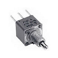
Manufacturer Part Number
P12TABS472MAB2
Description
TRIMMERS & POTENTIOMETERS SFERNICE / P12 T M 4K7 20% A BO E3
Manufacturer
Vishay
Type
Potentiometerr
Datasheet
1.P12TABS472MAB2.pdf
(5 pages)
Specifications of P12TABS472MAB2
Resistance
4.7kohm
Power Rating
1W
Tolerance (+ Or -)
20%
Number Of Turns
1Turn
Technology
Cermet
Mounting Style
Panel
Termination Style
Pin
Operating Temp Range
-55C to 125C
Failure Rate
Not Required
Shaft Diameter (mm)
3mm
Product Diameter (mm)
Not Requiredmm
Product Length (mm)
12mm
Product Height (mm)
22.7mm
Product Depth (mm)
12mm
Temperature Coefficient
±100
Lead Free Status / RoHS Status
Compliant


Document Number: 51033
Revision: 06-Jul-06
VALUES
RESIS-
TANCE
STAN-
DARD
100K
220K
470K
2.2M
4.7M
2.2K
4.7K
PERFORMANCE
Load Life
Climatic Sequence
Long Term Damp Heat
Rapid Temperature Change
Shock
Vibration
Rotational Life
STANDARD RESISTANCE ELEMENT DATA
10M
10K
22K
47K
100
220
470
1M
22
47
1K
Ω
AT 70 °C
POWER
MAX.
0.56
0.26
0.12
0.05
0.02
0.01
W
1
1
TESTS
LINEAR LAW
WORKING
VOLTAGE
148.3
216.7
316.2
MAX.
4.69
6.85
14.8
21.6
31.6
46.9
63.5
100
350
350
350
350
350
350
10
V
WIPER
213.2
145.8
MAX.
CUR.
67.4
46.1
31.6
21.3
14.5
3.16
1.59
0.75
0.35
0.16
0.07
0.01
100
mA
6.7
4.6
10
AT 70 °C
POWER
MAX.
0.26
0.12
0.05
0.5
0.5
Fully Sealed Container Cermet Potentiometers
W
LOGS LAW
WORKING
VOLTAGE
90’/30’ - ambient temp. 70 °C
MAX.
22.4
33.2
48.5
79.7
Phase A dry heat 125 °C
Phase B damp heat
Phase C cold - 55 °C
Phase D damp heat 5 cycles
105
153
224
332
350
350
350
1000 hours at rated power
V
For technical questions, contact: sfer@vishay.com
Military and Professional Grade
40 °C
3 successive shocks
- 55 °C at + 125 °C
0.75 mm or 10 g
CONDITIONS
during 6 hours
50 g at 11 ms
in 3 directions
25 000 cycles
WIPER
MAX.
CUR.
22.4
15.1
10.3
7.07
4.77
3.26
2.24
1.51
0.74
0.35
0.16
10 - 55 Hz
mA
5 cycles
56 days
See also: Application notes
+ 125 °C
ppm/°C
93 % RH
- 55 °C
+ 200
± 100
TCR
0
MARKING
Printed:
- VISHAY trademark
- series
- ohmic value (in Ω )
- tolerance (in %)
- manufacturing date
- marking of terminals 1 or a
SPECIAL FEATURES
SHAFTS
Lengths are measured from the mounting surface to the free
end of shaft. Shaft slot is aligned with the wiper within ± 10°.
Special shafts are available, in accordance with drawings
supplied by customers. We recommend customers not to
machine shafts, in order to avoid damage. Bending or torsion
of terminal should be avoided.
SHAFT AND PANEL SEALING HARDWARE
The type P12T with R or M shaft can be provided with an
optional “DE” sealing hardware which ensures sealing of
both the shaft and the mounting panel. “DE” sealing
hardware can be supplied in a separate envelope.
SHAFT LOCKING
- The shaft locking bushing is available only with P12H
potentiometers. Torque applied to locking nuts should not
exceed 15 Ncm.
± 1 %
Contact res. variation: < 3 % Rn
± 0.5 %
± 0.5 %
Dielectric strength: 1000 V RMS
Insulation resistance: > 10
± 0.1 %
± 0.1 %
± 3 %
Contact res. variation: < 2 % Rn
± 0.5 %
ΔRT
RT
(%)
TYPICAL VALUES AND DRIFTS
4
MΩ
Vishay Sfernice
ΔV
V
1-2
1-3
www.vishay.com
ΔR
R
1-2
1-2
≤ ± 0.2 %
± 0.2 %
P12
(%)
± 1 %
± 1 %
115
Related parts for P12TABS472MAB2
Image
Part Number
Description
Manufacturer
Datasheet
Request
R

Part Number:
Description:
357-036-542-201 CARDEDGE 36POS DL .156 BLK LOPRO
Manufacturer:
Vishay
Datasheet:
Part Number:
Description:
357-036-542-201 CARDEDGE 36POS DL .156 BLK LOPRO
Manufacturer:
Vishay
Datasheet:
Part Number:
Description:
357-036-542-201 CARDEDGE 36POS DL .156 BLK LOPRO
Manufacturer:
Vishay
Datasheet:
Part Number:
Description:
357-036-542-201 CARDEDGE 36POS DL .156 BLK LOPRO
Manufacturer:
Vishay
Datasheet:
Part Number:
Description:
357-036-542-201 CARDEDGE 36POS DL .156 BLK LOPRO
Manufacturer:
Vishay
Datasheet:
Part Number:
Description:
357-036-542-201 CARDEDGE 36POS DL .156 BLK LOPRO
Manufacturer:
Vishay
Datasheet:
Part Number:
Description:
357-036-542-201 CARDEDGE 36POS DL .156 BLK LOPRO
Manufacturer:
Vishay
Datasheet:
Part Number:
Description:
357-036-542-201 CARDEDGE 36POS DL .156 BLK LOPRO
Manufacturer:
Vishay
Datasheet:
Part Number:
Description:
357-036-542-201 CARDEDGE 36POS DL .156 BLK LOPRO
Manufacturer:
Vishay
Datasheet:
Part Number:
Description:
357-036-542-201 CARDEDGE 36POS DL .156 BLK LOPRO
Manufacturer:
Vishay
Datasheet:
Part Number:
Description:
357-036-542-201 CARDEDGE 36POS DL .156 BLK LOPRO
Manufacturer:
Vishay
Datasheet:
Part Number:
Description:
357-036-542-201 CARDEDGE 36POS DL .156 BLK LOPRO
Manufacturer:
Vishay
Datasheet:
Part Number:
Description:
357-036-542-201 CARDEDGE 36POS DL .156 BLK LOPRO
Manufacturer:
Vishay
Datasheet:
Part Number:
Description:
357-036-542-201 CARDEDGE 36POS DL .156 BLK LOPRO
Manufacturer:
Vishay
Datasheet:
Part Number:
Description:
357-036-542-201 CARDEDGE 36POS DL .156 BLK LOPRO
Manufacturer:
Vishay
Datasheet: