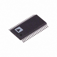
AD5557CRU-REEL7 Analog Devices Inc, AD5557CRU-REEL7 Datasheet - Page 14

AD5557CRU-REEL7
Manufacturer Part Number
AD5557CRU-REEL7
Description
IC,D/A CONVERTER,DUAL,14-BIT,TSSOP,38PIN
Manufacturer
Analog Devices Inc
Datasheet
1.AD5547BRUZ.pdf
(20 pages)
Specifications of AD5557CRU-REEL7
Design Resources
Precision, Unipolar, Inverting Conversion Using AD5547/57 DAC (CN0026) Precision, Unipolar, Noninverting Configuration for the AD5547/57 DAC (CN0027) Precision, Bipolar, Configuration for AD5547/AD5557 DAC (CN0028)
Settling Time
500ns
Number Of Bits
14
Data Interface
Parallel
Number Of Converters
2
Voltage Supply Source
Single Supply
Power Dissipation (max)
55µW
Operating Temperature
-40°C ~ 125°C
Mounting Type
Surface Mount
Package / Case
38-TSSOP
Lead Free Status / RoHS Status
Contains lead / RoHS non-compliant
AD5547/AD5557
APPLICATIONS INFORMATION
UNIPOLAR MODE
2-Quadrant Multiplying Mode, V
The AD5547/AD5557 DAC architecture uses a current-steering
R-2R ladder design that requires an external reference and op
amp to convert the unipolar mode of the output voltage to
where D is the decimal equivalent of the input code.
V
V
OUT
OUT
= −V
= −V
+5V
REF
REF
1µF
C1
× D/65,536 (AD5547)
× D/16,384 (AD5557)
16/14 DATA
C2
0.1µF
A0, A1
LDAC
MSB
0.1µF
4
WR
RS
C3
V
GND
IN
2
TRIM
V
OUT
OUT
U3
VDD
WR
= 0 V to –V
ADR03
Figure 20. Unipolar 2-Quadrant Multiplying Mode, V
5
6
LDAC
AD5547/AD5557
R1
R
1A
RS
U1
REF
MSB A0, A1
R
COMA
R2
V
REFA
Rev. B | Page 14 of 20
2
(1)
(2)
+2.5V
R
16-/14-BIT
OFSA
ROFS
2.5V
In this case, the output voltage polarity is opposite the V
polarity (see Figure 20). Table 7 shows the negative output vs.
code for the AD5547.
Table 7. AD5547 Unipolar Mode Negative Output vs. Code
D in Binary
1111 1111 1111 1111
1000 0000 0000 0000
0000 0000 0000 0001
0000 0000 0000 0000
R
RFB
FBA
AGNDA
OUT
I
OUTA
= 0 to –V
C6
REF
6.8pF
AD8628
+V
–V
–5V
V
–V
–V
–V
0
C4
C5
OUT
REF
REF
REF
1µF
0.1µF
(V)
/2
(65,535/65,536)
(1/65,536)
–2.5V TO 0V
V
OUTA
REF


