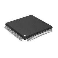
AD8191ASTZ Analog Devices Inc, AD8191ASTZ Datasheet - Page 20

AD8191ASTZ
Manufacturer Part Number
AD8191ASTZ
Description
IC,Telecom Switching Circuit,QFP,100PIN,PLASTIC
Manufacturer
Analog Devices Inc
Datasheet
1.AD8191ASTZ-RL.pdf
(32 pages)
Specifications of AD8191ASTZ
Function
Switch
Circuit
1 x 4:1
On-state Resistance
100 Ohm
Voltage Supply Source
Single Supply
Voltage - Supply, Single/dual (±)
3 V ~ 3.6 V
Operating Temperature
-40°C ~ 85°C
Mounting Type
Surface Mount
Package / Case
100-LQFP
Lead Free Status / RoHS Status
Lead free / RoHS Compliant
Available stocks
Company
Part Number
Manufacturer
Quantity
Price
Company:
Part Number:
AD8191ASTZ
Manufacturer:
ADI
Quantity:
180
Company:
Part Number:
AD8191ASTZ
Manufacturer:
Analog Devices Inc
Quantity:
10 000
Part Number:
AD8191ASTZ
Manufacturer:
ADI/亚德诺
Quantity:
20 000
Company:
Part Number:
AD8191ASTZ-RL
Manufacturer:
Analog Devices Inc
Quantity:
10 000
Company:
Part Number:
AD8191ASTZ/XST
Manufacturer:
ADI
Quantity:
210
AD8191
Table 9. Dual Mode, 2× [8:1], High Speed Switch Mapping
HS_CH[3:0]
X000
X001
X010
X011
X100
X101
X110
X111
Table 10. Single Mode, 1× [16:1], High Speed Switch
Mapping
HS_CH[3:0]
0000
0001
0010
0011
0100
0101
0110
0111
1000
1001
1010
1011
1100
1101
1110
1111
O[3:2]
A1
A3
B1
B3
C1
C3
D1
D3
O[3:0]
A0
A1
A2
A3
B0
B1
B2
B3
C0
C1
C2
C3
D0
D1
D2
D3
A0
A2
B0
B2
C0
C2
D0
D2
High Speed Channel A0 switched to
output
High Speed Channel A1 switched to
output
High Speed Channel A2 switched to
output
High Speed Channel A3 switched to
output
High Speed Channel B0 switched to
output
High Speed Channel B1 switched to
output
High Speed Channel B2 switched to
output
High Speed Channel B3 switched to
output
High Speed Channel C0 switched to
output
High Speed Channel C1 switched to
output
High Speed Channel C2 switched to
output
High Speed Channel C3 switched to
output
High Speed Channel D0 switched to
output
High Speed Channel D1 switched to
output
High Speed Channel D2 switched to
output
High Speed Channel D3 switched to
output
O[1:0]
Description
Description
The A0 and A1 high speed
channels switched to output
The A2 and A3 high speed
channels switched to output
The B0 and B1 high speed
channels switched to output
The B2 and B3 high speed
channels switched to output
The C0 and C1 high speed
channels switched to output
The C2 and C3 high speed
channels switched to output
The D0 and D1 high speed
channels switched to output
The D2 and D3 high speed
channels switched to output
Rev. 0 | Page 20 of 32
AUXILIARY DEVICE MODES REGISTER
AUX_EN: Auxiliary (Low Speed) Switch Enable Bit
Table 11. AUX_EN Description
AUX_EN
0
1
AUX_SM[1:0]: Auxiliary (Low Speed) Switching Mode
Select Bus
Table 12. AUX_SM[1:0] Description
AUX_SM[1:0]
00
01
10
11
AUX_CH[3:0]: Auxiliary (Low Speed) Switch Source
Select Bus
Table 13. Quad Mode, 4× [4:1], Auxiliary Switch Mapping
AUX_CH[3:0]
XX00
XX01
XX10
XX11
Description
Auxiliary switch off, no low speed input/output
to low speed common input/output
connection
Auxiliary switch on
AUX_COM[3:0]
AUX_A[3:0]
AUX_B[3:0]
AUX_C[3:0]
AUX_D[3:0]
Description
Quad Mode, 4× [4:1]
Dual Mode, 2× [8:1]
Single Mode, 1× [6:1]
Illegal value; previous value of AUX_SM[1:0]
retained
Description
Auxiliary Source A switched
to output
Auxiliary Source B switched
to output
Auxiliary Source C switched
to output
Auxiliary Source D switched
to output


