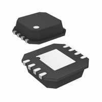
ADA4941-1YCPZ-R7 Analog Devices Inc, ADA4941-1YCPZ-R7 Datasheet - Page 19

ADA4941-1YCPZ-R7
Manufacturer Part Number
ADA4941-1YCPZ-R7
Description
Amplifier, Other
Manufacturer
Analog Devices Inc
Type
ADC Driverr
Datasheet
1.ADA4941-1YCPZ-R7.pdf
(24 pages)
Specifications of ADA4941-1YCPZ-R7
Design Resources
Converting a Single-Ended Signal with AD7982 Differential PulSAR ADC (CN0032) Converting a Single-Ended Signal with AD7984 Differential PulSAR ADC (CN0033)
Applications
Data Acquisition
Mounting Type
Surface Mount
Package / Case
8-LFCSP
Lead Free Status / RoHS Status
Lead free / RoHS Compliant
Other names
ADA4941-1YCPZ-R7TR
Available stocks
Company
Part Number
Manufacturer
Quantity
Price
Company:
Part Number:
ADA4941-1YCPZ-R7
Manufacturer:
Intersil
Quantity:
254
FREQUENCY RESPONSE VS. CLOSED-LOOP GAIN
The operational amplifiers used in the ADA4941-1 are voltage
feedback with an open-loop frequency response that can be
approximated with the integrator response, as shown in Figure 53.
For each amplifier, the frequency response can be approximated
by the following equations:
f
open-loop gain shown in Figure 53 equals 1). f
amplifiers is about 50 MHz.
CR
is the gain-bandwidth frequency of the amplifier (where the
(Noninverting Response)
(Inverting Response)
V
V
Figure 53. ADA4941-1 Op Amp Open-Loop Gain vs. Frequency
100
O
O
80
60
40
20
0.001
_A1
_A2
0
=
=
VIN
VIN
0.01
×
×
⎛
⎜
⎜
⎝
⎛ −
⎜
⎜
⎝
1
+
R
R
G
R
R
F
FREQUENCY (MHz)
F
G
⎞
× ⎟ ⎟
⎠
0.1
⎞
× ⎟ ⎟
⎠
⎛
⎜
⎜
⎜
⎜
⎜
⎝
⎛
⎜
⎜
⎜
⎜
⎜
⎝
1
1
+
+
⎡
⎢
⎣
⎡
⎢
⎣
R
R
F
1
F
R
+
R
G
+
1
G
R
1
R
G
G
⎤
⎥
⎦
⎤
⎥
⎦
×
CR
fcr = 50MHz
×
10
fcr
f
for both
fcr
f
⎞
⎟
⎟
⎟
⎟
⎟
⎠
⎞
⎟
⎟
⎟
⎟
⎟
⎠
100
(15)
(16)
Rev. B | Page 19 of 24
The inverting amplifier A2 has a fixed feedback network. The
transfer function is approximately
A1’s frequency response depends on the external feedback
network as indicated by Equation 15. The overall differential
output voltage is therefore
V
Multiplying the terms and neglecting negligible terms leads to
the following approximation:
There are two poles in this transfer function, and the lower
frequency pole limits the bandwidth of the differential
amplifier. If VOP is shorted to IN− (A1 is a unity gain follower),
the 25 MHz closed-loop bandwidth of the inverting channel
limits the overall bandwidth. When A1 is operating with higher
noise gains, the bandwidth is limited by A1’s closed-loop
bandwidth, which is inversely proportional to the noise gain
(1 + R
provides a noise gain of 10, the bandwidth drops to 5 MHz.
V
V
V
⎛
⎜
⎜
⎜
⎜
⎝
⎡
⎢
⎢
⎢
⎢
⎢
⎣
1
O
⎛
⎜
⎜
⎝
O
O
O
, dm = VOP − VON = VOP + VOP ×
1
+
, dm
,
_
dm
+
1
A
⎡
⎢
⎣
F
+
2
/R
R
=
=
25
=
F
G
VIN
VIN
R
1
). For instance, if the external feedback network
−
+
MHz
G
f
VIN
R
G
⎛
⎜
⎜
⎝
×
1
⎤
⎥
⎦
⎛
⎜
⎜
⎝
+
×
×
1
⎞
⎟
⎟
⎟
⎟
⎠
R
+
R
50
⎛
⎜
⎜
⎜
⎜
⎜
⎝
1
G
F
R
R
+
MHz
⎞
× ⎟ ⎟
⎠
G
2
F
f
50
⎞
× ⎟ ⎟
⎠
2
1
MHz
×
⎛
⎜
⎜
⎜
⎜
⎜
⎝
⎞
⎟
⎟
⎠
1
×
f
+
⎛
⎜
⎜
⎝
1
⎡
⎢
⎣
+
⎞
⎟
⎟
⎟
⎟
⎟
⎠
R
=
F
25
R
−
+
G
MHz
VOP
R
f
G
1
⎛
⎜
⎜
⎜
⎜
⎝
⎤
⎥
⎦
1
×
×
⎞
⎟
⎟
⎠
+
50
⎤
⎥
⎥
⎥
⎥
⎥
⎦
⎛
⎜
⎜
⎜
⎜
⎝
1
25
ADA4941-1
MHz
+
1
f
MHz
25
f
1
MHz
f
⎞
⎟
⎟
⎟
⎟
⎟
⎠
×
⎞
⎟
⎟
⎟
⎟
⎠
⎞
⎟
⎟
⎟
⎟
⎠
(18)
(19)
(20)
(17)


