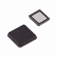
ADV7179KCPZ-REEL Analog Devices Inc, ADV7179KCPZ-REEL Datasheet - Page 33

ADV7179KCPZ-REEL
Manufacturer Part Number
ADV7179KCPZ-REEL
Description
Chip Scale NTSC/PAL Vid Encoder APM I.C.
Manufacturer
Analog Devices Inc
Type
Video Encoderr
Datasheet
1.ADV7179KCPZ.pdf
(52 pages)
Specifications of ADV7179KCPZ-REEL
Applications
Digital Cameras, Mobile Phones, Portable Video
Voltage - Supply, Analog
2.8 V, 3.3 V
Mounting Type
Surface Mount
Package / Case
40-LFCSP
Lead Free Status / RoHS Status
Lead free / RoHS Compliant
Voltage - Supply, Digital
-
Lead Free Status / RoHS Status
Lead free / RoHS Compliant
Other names
ADV7179KCPZ-REELTR
Available stocks
Company
Part Number
Manufacturer
Quantity
Price
Company:
Part Number:
ADV7179KCPZ-REEL
Manufacturer:
TI
Quantity:
69 456
Part Number:
ADV7179KCPZ-REEL
Manufacturer:
ADI/亚德诺
Quantity:
20 000
TIMING MODE REGISTER 0 (TR0)
Bits:
Address:
Figure 43 shows the various operations under the control of Timing Register 0. This register can be read from as well as written to.
Table 15. TR0 Bit Description
Bit Name
Master/Slave Control
Timing Mode Selection
BLANK Input Control
Luma Delay
Pixel Port Control
Timing Register Reset
TR07–TR00
SR4–SR0 = 07H
REGISTER RESET
TR07
TIMING
TR07
TR06
0
1
Bit No.
TR00
TR02–TR01
TR03
TR05–TR04
TR06
TR07
PIXEL PORT
CONTROL
8 BIT
FORBIDDEN
TR06
TR05 TR04
TR05
0
0
1
1
LUMA DELAY
0
1
0
1
Description
This bit controls whether the ADV7174/ADV7179 is in master or slave mode.
These bits control the timing mode of the ADV7174/ADV7179. These modes are
described in more detail in the 3.3 V Timing Specifications table.
This bit controls whether the BLANK input is used when the part is in slave mode.
These bits control the addition of a luminance delay. Each bit represents a delay of
74 ns.
This bit is used to set the pixel port to accept 8-bit or YCrCb data on Pins P7–P0.
0 must be written here.
Toggling the TR07 from low to high and to low again resets the internal timing
counters. This bit should be toggled after power-up, reset, or changing to a new
timing mode.
Figure 43. Timing Register 0
Rev. B | Page 33 of 52
TR04
0ns DELAY
74ns DELAY
148ns DELAY
222ns DELAY
TR03
BLANK INPUT
0
1
CONTROL
TR03
ENABLE
DISABLE
TR02 TR01
0
0
1
1
TIMING MODE
TR02
SELECTION
0
1
0
1
MODE 0
MODE 1
MODE 2
MODE 3
TR01
TR00
0
1
MASTER/SLAVE
CONTROL
SLAVE TIMING
MASTER TIMING
TR00
ADV7174/ADV7179


