DG213DQ-T1-E3 Vishay, DG213DQ-T1-E3 Datasheet - Page 3
DG213DQ-T1-E3
Manufacturer Part Number
DG213DQ-T1-E3
Description
2 NORM OPEN, 2 NORM CLOSED ANALOG SWITCH
Manufacturer
Vishay
Datasheet
1.DG213DY-T1-E3.pdf
(8 pages)
Specifications of DG213DQ-T1-E3
Function
Switch
Circuit
4 x SPST - NC/NO
On-state Resistance
85 Ohm
Current - Supply
5µA
Operating Temperature
-40°C ~ 85°C
Mounting Type
Surface Mount
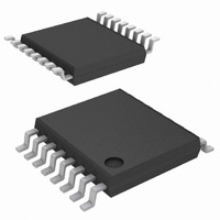
Package / Case
16-TSSOP
Number Of Switches
Quad
Switch Configuration
SPST
On Resistance (max)
110 Ohms @ 12 V
On Time (max)
200 ns @ 12 V
Off Time (max)
100 ns @ +/- 15 V
Off Isolation (typ)
90 dB
Supply Voltage (max)
40 V
Supply Voltage (min)
3 V
Maximum Power Dissipation
500 mW
Maximum Operating Temperature
+ 85 C
Mounting Style
SMD/SMT
Minimum Operating Temperature
- 40 C
Off State Leakage Current (max)
+/- 5 nA
Switch Current (typ)
30 mA
Lead Free Status / RoHS Status
Lead free / RoHS Compliant
Lead Free Status / RoHS Status
Lead free / RoHS Compliant
Other names
DG213DQ-T1-E3TR
Available stocks
Company
Part Number
Manufacturer
Quantity
Price
Company:

Part Number:
DG213DQ-T1-E3
Manufacturer:
Vishay
Quantity:
8 344


Notes:
a.
b.
c.
d.
e.
Document Number: 70662
S-00787—Rev. F, 17-Apr-00
Power Supply
Positive Supply Current
Negative Supply Current
Logic Supply Current
Power Supply Range for
Continuous Operation
Analog Switch
Analog Signal Range
Drain-Source On-Resistance
Dynamic Characteristics
Turn-On Time
Turn-Off Time
Break-Before-Make Time Delay
Charge Injection
Power Supply
Positive Supply Current
Negative Supply Current
Logic Supply Current
Power Supply Range for
Continuous Operation
Room = 25 C, Full = as determined by the operating temperature suffix.
Typical values are for DESIGN AID ONLY, not guaranteed nor subject to production testing.
The algebraic convention whereby the most negative value is a minimum and the most positive a maximum, is used in this data sheet.
Guaranteed by design, not subject to production test.
V
IN
= input voltage to perform proper function.
Parameter
Parameter
d
Symbol
V
r
ANALOG
DS(on)
t
V
t
OFF
Symbol
ON
t
I+
I–
Q
I
OP
D
L
V
I+
I–
I
OP
L
Unless Otherwise Specified
Unless Otherwise Specified
C
L
V
= 1 nF, V
L
V
V
V
Test Conditions
= 5 V, V
L
D
V+ = 12 V, V– = 0 V
S
V+ = 15 V, V– = –15 V
Test Conditions
= 5 V, V
= 3 V, 8 V, I
= 8 V, See Figure 3
V
V
See Figure 2
See Figure 2
IN
IN
V
V
gen
IN
IN
IN
= 0 or 5 V
= 0 or 5 V
IN
= 0 or 5 V
= 0 or 5 V
= 6 V, R
= 2.4 V, 0.8 V
= 2.4 V, 0.8 V
S
= 1 mA
gen
= 0
e
e
Temp
Temp
Room
Room
Room
Room
Room
Room
Room
Room
Room
Room
Room
Full
Full
Full
Full
Full
Full
Full
Full
Full
Full
a
a
Min
Min
–1
–5
V–
50
–1
–5
www.vishay.com FaxBack 408-970-5600
3
3
c
c
–40 to 85 C
–40 to 85 C
Vishay Siliconix
D Suffix
D Suffix
Typ
Typ
125
90
45
80
4
b
b
Max
Max
140
200
100
110
V+
1
5
1
5
1
5
1
5
22
40
DG213
c
c
Unit
Unit
pC
ns
V
V
V
A
A
A
A
4-3
Related parts for DG213DQ-T1-E3
Image
Part Number
Description
Manufacturer
Datasheet
Request
R

Part Number:
Description:
Quad Complementary CMOS Analog Switch
Manufacturer:
TEMICs
Datasheet:

Part Number:
Description:
357-036-542-201 CARDEDGE 36POS DL .156 BLK LOPRO
Manufacturer:
Vishay
Datasheet:
Part Number:
Description:
357-036-542-201 CARDEDGE 36POS DL .156 BLK LOPRO
Manufacturer:
Vishay
Datasheet:
Part Number:
Description:
357-036-542-201 CARDEDGE 36POS DL .156 BLK LOPRO
Manufacturer:
Vishay
Datasheet:
Part Number:
Description:
357-036-542-201 CARDEDGE 36POS DL .156 BLK LOPRO
Manufacturer:
Vishay
Datasheet:
Part Number:
Description:
357-036-542-201 CARDEDGE 36POS DL .156 BLK LOPRO
Manufacturer:
Vishay
Datasheet:
Part Number:
Description:
357-036-542-201 CARDEDGE 36POS DL .156 BLK LOPRO
Manufacturer:
Vishay
Datasheet:
Part Number:
Description:
357-036-542-201 CARDEDGE 36POS DL .156 BLK LOPRO
Manufacturer:
Vishay
Datasheet:
Part Number:
Description:
357-036-542-201 CARDEDGE 36POS DL .156 BLK LOPRO
Manufacturer:
Vishay
Datasheet:
Part Number:
Description:
357-036-542-201 CARDEDGE 36POS DL .156 BLK LOPRO
Manufacturer:
Vishay
Datasheet:
Part Number:
Description:
357-036-542-201 CARDEDGE 36POS DL .156 BLK LOPRO
Manufacturer:
Vishay
Datasheet:
Part Number:
Description:
357-036-542-201 CARDEDGE 36POS DL .156 BLK LOPRO
Manufacturer:
Vishay
Datasheet:
Part Number:
Description:
357-036-542-201 CARDEDGE 36POS DL .156 BLK LOPRO
Manufacturer:
Vishay
Datasheet:
Part Number:
Description:
357-036-542-201 CARDEDGE 36POS DL .156 BLK LOPRO
Manufacturer:
Vishay
Datasheet: