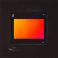
MT9V022I77ATC Aptina LLC, MT9V022I77ATC Datasheet - Page 33

MT9V022I77ATC
Manufacturer Part Number
MT9V022I77ATC
Description
IC SENSOR IMAGE VGA COLOR 52IBGA
Manufacturer
Aptina LLC
Type
CMOS Imagingr
Series
DigitalClarity®r
Specifications of MT9V022I77ATC
Pixel Size
6µm x 6µm
Active Pixel Array
752H x 480V
Frames Per Second
60
Voltage - Supply
3.3V
Package / Case
52-IBGA
Sensor Image Color Type
Color
Sensor Image Size Range
250,920 to 480,000Pixels
Sensor Image Size
752x480Pixels
Operating Supply Voltage (min)
3V
Operating Supply Voltage (typ)
3.3V
Operating Supply Voltage (max)
3.6V
Operating Temp Range
-40C to 85C
Package Type
IBGA
Operating Temperature Classification
Industrial
Mounting
Surface Mount
Pin Count
52
Lead Free Status / RoHS Status
Lead free / RoHS Compliant
Other names
557-1267
MT9V022I77ATC
MT9V022I77ATC
Hard Reset of Logic
Soft Reset of Logic
STANDBY Control
Monitor Mode Control
PDF: 3295348826/Source:7478516499
MT9V022_DS - Rev.H 6/10 EN
The RC circuit for the MT9V022 uses a 10kΩ resistor and a 0.1μF capacitor. The rise time
for the RC circuit is 1μs maximum.
Soft reset of logic is controlled by:
• R0x0C Reset
Bit 0 is used to reset the digital logic of the sensor while preserving the existing two-wire
serial interface configuration. Furthermore, by asserting the soft reset, the sensor aborts
the current frame it is processing and starts a new frame. Bit 1 is a shadowed reset
control register bit to explicitly reset the automatic gain and exposure control feature.
These two bits are self-resetting bits and also return to “0” during two-wire serial inter-
face reads.
The sensor goes into standby mode by setting STANDBY to HIGH. Once the sensor
detects that STANDBY is asserted, it completes the current frame before disabling the
digital logic, internal clocks, and analog power enable signal. To release the sensor out
from the standby mode, reset STANDBY back to LOW. The LVDS must be powered to
ensure that the device is in standby mode. See "Appendix B – Power-On
Reset and Standby Timing" on page 52 for more information on standby.
Monitor mode is controlled by:
• R0x0E Monitor Mode Enable
• R0xC0 Monitor Mode Image Capture Control
The sensor goes into monitor mode when R0x0E bit 0 is set to HIGH. In this mode, the
sensor first captures a programmable number of frames (R0xC0), then goes into a sleep
period for five minutes. The cycle of sleeping for five minutes and waking up to capture a
number of frames continues until R0x0E bit 0 is cleared to return to normal operation.
In some applications when monitor mode is enabled, the purpose of capturing frames is
to calibrate the gain and exposure of the scene using automatic gain and exposure
control feature. This feature typically takes less than 10 frames to settle. In case a larger
number of frames is needed, the value of R0xC0 may be increased to capture more
frames.
During the sleep period, none of the analog circuitry and a very small fraction of digital
logic (including a five-minute timer) is powered. The master clock (SYSCLK) is therefore
always required.
33
MT9V022: 1/3-Inch Wide-VGA Digital Image Sensor
Aptina reserves the right to change products or specifications without notice.
©2005 Aptina Imaging Corporation. All rights reserved.
Feature Description


