196 TPI (Test Products Int), 196 Datasheet - Page 13
196
Manufacturer Part Number
196
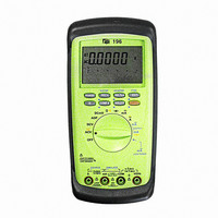
Description
DMM AUTO-RANGE 0-24MA OUTPUT
Manufacturer
TPI (Test Products Int)
Series
190r
Type
Digital (DMM)r
Specifications of 196
Includes
Battery, Test Leads
Style
Handheld
Display Digits
4.75
Display Type
LCD, Bar Graph
Display Count
50000
Function
Voltage, Current, Resistance
Functions, Extra
Continuity, Diode Test
Features
Auto Off, Backlight, Hold, Min/Max, RS-232 Port, Sleep
Ranging
Auto/Manual
Response
Average
Lead Free Status / RoHS Status
Vendor undefined / Vendor undefined
Other names
196TPI
196TPI
290-1425
TPI 196
TPI196
196TPI
290-1425
TPI 196
TPI196
Available stocks
Company
Part Number
Manufacturer
Quantity
Price

Company:
Part Number:
196-015-112-001
Manufacturer:
NorComp Inc.
Quantity:
457
Company:
Part Number:
196-015-112-031
Manufacturer:
NorComp Inc.
Quantity:
457
Company:
Part Number:
196-015-112-551
Manufacturer:
NorComp Inc.
Quantity:
457
Company:
Part Number:
196-015-113L001
Manufacturer:
NorComp Inc.
Quantity:
457


23
e. Measuring Resistance
Instrument set-up:
FUNCTION
Do not attempt to make resistance measurements with
circuit energized. For best results, remove the resistor
completely from the circuit before attempting to measure
it.
NOTE:
To make accurate low ohm measurements, short the ends
of test leads together and record the resistance reading.
Deduct this value from actual readings.
Measurement Procedure:
1. Disconnect power to circuit to be measured.
2. Plug black test lead into the
3. Plug red test lead into
4. Set the rotary switch on the DMM to the
5.Connect the test leads to the circuit to be measured.
6. Read the resistance value on the LCD.
WARNING!
COM
BLACK
TEST LEAD
RED
TEST LEAD
COM
input jack.
MINIMUM
READING
0.01Ω
input jack.
50.000MΩ
MAXIMUM
READING
function.
f. Measuring Diodes
Instrument set-up:
FUNCTION
CAUTION
Do not attempt to make diode measurements with circuit
energized. The only way to accurately test a diode is to
remove it completely from the circuit before attempting to
measure it.
Measurement Procedure:
1. Disconnect power to circuit to be measured.
2. Plug black test lead into the
3. Plug red test lead into
4. Set the rotary switch to the
5. Connect the black test lead to the banded end of the diode
6. Reading on the display should be between 0.5 and 0.8
7. Reading test lead connections in 5 above.
8. Reading on the display should be OFL(Overflow).
NOTE: If diode reads 0 in both directions, diode is
shorted. If diode reads OFL in both directions, diode
is open.
and the red test lead to the non-banded end of the diode.
volts.
BLACK
TEST LEAD
COM
RED
TEST LEAD
COM
input jack.
function.
MINIMUM
READING
0.001V
input jack.
MAXIMUM
READING
2.0000V
24