122NQ030PBF Vishay, 122NQ030PBF Datasheet - Page 2
122NQ030PBF
Manufacturer Part Number
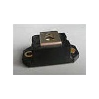
122NQ030PBF
Description
Schottky (Diodes & Rectifiers) 120 Amp 30 Volt
Manufacturer
Vishay
Datasheet
1.122NQ030PBF.pdf
(7 pages)
Specifications of 122NQ030PBF
Product
Schottky Rectifiers
Peak Reverse Voltage
30 V
Forward Continuous Current
120 A
Max Surge Current
22500 A
Configuration
Single
Forward Voltage Drop
0.59 V at 240 A
Maximum Reverse Leakage Current
10000 uA
Operating Temperature Range
- 55 C to + 150 C
Mounting Style
Screw
Package / Case
D-67
Lead Free Status / RoHS Status
Lead free / RoHS Compliant


Document Number: 94128
122NQ030PbF
Bulletin PD-21141
Absolute Ma x i mum Ratings
Electrical Specifications
Thermal-Mechanical Specifications
Voltage Ratings
I
I
E
I
V
I
C
L
dv/dt Ma x . Voltage Rate of Change
T
T
R
R
wt
T
V
V
FSM
F(AV)
AR
RM
S
AS
J
FM
T
stg
R
RW M
thJC
thCS
Ma x . Average Forward Current
Max . Peak One Cycle Non-Repetitive
Surge Current * See Fig. 7
Non-Repetitive Avalanche Energy
Repetitive Avalanche Current
* See Fig. 5
Parameters
Part number
Max . DC Reverse Voltage (V)
Max . W o rking Peak Reverse Voltage (V)
Parameters
Max . Forward Voltage Drop
(Per Leg) * See Fig. 1
Max . Reverse Leakage Current
(Per Leg) * See Fig. 2
Max . Junction Capacitance
Typical Series Inductance
(Rated V
Parameters
Ma x . Junction Temperature Range
Ma x . Storage Temperature Range
Ma x . Thermal Resistance Junction
to Case
Typical Thermal Resistance, Case to
Heatsink
Appro x i mate W e ight
Mounting Torque
Terminal Torque
Case Style
R
)
05/06
(1)
(1)
Min.
Ma x .
Min.
Ma x .
30 (1.06)
-55 to 150
-55 to 150
4 (35.4)
5 (44.2)
122NQ Units Conditions
122NQ Units
122NQ Units
3 (26.5)
3.4 (30)
18000
10000
560
2000
10
7400
0.57
0.75
0.47
0.67
0.38
0.05
120
54
12
7.0
HALF PAK Module
g (oz.)
(Ibf-in)
mA
V/ μs
°C/W
°C/W
mA
Nm
mJ
pF
nH
°C
°C
A
A
A
V
V
V
V
DC operation
T
T
50% duty cycle @ T
5μs Sine or 3μs Rect. pulse
10ms Sine or 6ms Rect. pulse
T
Current decaying linearly to zero in 1 μsec
Frequency limited by T
@ 120A
@ 240A
@ 120A
@ 240A
V
From top of terminal hole to mounting plane
Mounting surface , smooth and greased
Non-lubricated threads
J
J
J
R
= 25 °C, I
= 125 °C
= 25 °C
= 5V
DC
(test signal range 100Khz to 1Mhz) 25°C
AS
Conditions
Conditions
122NQ030PbF
= 11 Amps, L = 1 mH
(1) Pulse W i dth < 300
V
T
T
R
J
J
C
= 25 °C
= 125 °C
= rated V
= 115 °C, rectangular wave form
* See Fig. 4
30
J
ma x . V
R
Following any rated
load condition and with
rated V
A
= 1.5 x V
μs, Duty Cycle < 2 %
www.vishay.com
RRM
R
applied
typical
2
Related parts for 122NQ030PBF
Image
Part Number
Description
Manufacturer
Datasheet
Request
R

Part Number:
Description:
357-036-542-201 CARDEDGE 36POS DL .156 BLK LOPRO
Manufacturer:
Vishay
Datasheet:
Part Number:
Description:
357-036-542-201 CARDEDGE 36POS DL .156 BLK LOPRO
Manufacturer:
Vishay
Datasheet:
Part Number:
Description:
357-036-542-201 CARDEDGE 36POS DL .156 BLK LOPRO
Manufacturer:
Vishay
Datasheet:
Part Number:
Description:
357-036-542-201 CARDEDGE 36POS DL .156 BLK LOPRO
Manufacturer:
Vishay
Datasheet:
Part Number:
Description:
357-036-542-201 CARDEDGE 36POS DL .156 BLK LOPRO
Manufacturer:
Vishay
Datasheet:
Part Number:
Description:
357-036-542-201 CARDEDGE 36POS DL .156 BLK LOPRO
Manufacturer:
Vishay
Datasheet:
Part Number:
Description:
357-036-542-201 CARDEDGE 36POS DL .156 BLK LOPRO
Manufacturer:
Vishay
Datasheet:
Part Number:
Description:
357-036-542-201 CARDEDGE 36POS DL .156 BLK LOPRO
Manufacturer:
Vishay
Datasheet:
Part Number:
Description:
357-036-542-201 CARDEDGE 36POS DL .156 BLK LOPRO
Manufacturer:
Vishay
Datasheet:
Part Number:
Description:
357-036-542-201 CARDEDGE 36POS DL .156 BLK LOPRO
Manufacturer:
Vishay
Datasheet:
Part Number:
Description:
357-036-542-201 CARDEDGE 36POS DL .156 BLK LOPRO
Manufacturer:
Vishay
Datasheet:
Part Number:
Description:
357-036-542-201 CARDEDGE 36POS DL .156 BLK LOPRO
Manufacturer:
Vishay
Datasheet:
Part Number:
Description:
357-036-542-201 CARDEDGE 36POS DL .156 BLK LOPRO
Manufacturer:
Vishay
Datasheet:
Part Number:
Description:
357-036-542-201 CARDEDGE 36POS DL .156 BLK LOPRO
Manufacturer:
Vishay
Datasheet:
Part Number:
Description:
357-036-542-201 CARDEDGE 36POS DL .156 BLK LOPRO
Manufacturer:
Vishay
Datasheet: