1N5822 ON Semiconductor, 1N5822 Datasheet
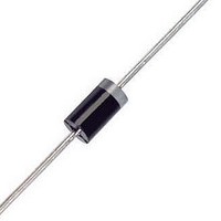
Schottky (Diodes & Rectifiers) 3A 40V

1N5822

Manufacturer Part Number
1N5822
Description
Schottky (Diodes & Rectifiers) 3A 40V
Manufacturer
ON Semiconductor
Datasheet

Specifications of 1N5822

Product
Schottky Diodes
Peak Reverse Voltage
40 V
Forward Continuous Current
3 A
Max Surge Current
80 A
Configuration
Single
Forward Voltage Drop
0.95 V @ 9.4 A
Maximum Reverse Leakage Current
2000 uA
Operating Temperature Range
- 65 C to + 125 C
Mounting Style
Through Hole
Package / Case
Case 267-05
Lead Free Status / RoHS Status
Lead free / RoHS Compliant

Available stocks

Company
Part Number
Manufacturer
Quantity
Price
Part Number:
1N5822
Manufacturer:
MICREL/麦瑞
Quantity:
20 000
Part Number:
1N5822 SSL34
Manufacturer:
JINGDAO/晶导
Quantity:
20 000
Part Number:
1N5822 X268
Manufacturer:
KEXIN/科信
Quantity:
20 000
Part Number:
1N5822-E
Manufacturer:
LRC/乐山
Quantity:
20 000
Part Number:
1N5822-E3/54
Manufacturer:
VISHAY/威世
Quantity:
20 000
Company:
Part Number:
1N5822-E3/54
Quantity:
70 000
Part Number:
1N5822-TP
Manufacturer:
MCC
Quantity:
157
Part Number:
1N5822G
Manufacturer:
ON
Quantity:
5 089
Part Number:
1N5822RL
Manufacturer:
STMicroelectronics
Quantity:
1 900
Part Number:
1N5822RL
Manufacturer:
ON Semiconductor
Quantity:
2
Part Number:
1N5822RLG
Manufacturer:
ON
Quantity:
30 000
Part Number:
1N5822RLG
Manufacturer:
ON
Quantity:
13 500
Part Number:
1N5822RLG
Manufacturer:
ON
Quantity:
19 884
Company:
Part Number:
1N5822RLG
Quantity:
2 250
Part Number:
1N5822U
Manufacturer:
ST
0
1N5820, 1N5821, 1N5822
Axial Lead Rectifiers
metal-to-silicon power diode. State-of-the-art geometry features
chrome barrier metal, epitaxial construction with oxide passivation
and metal overlap contact. Ideally suited for use as rectifiers in
low-voltage, high-frequency inverters, free wheeling diodes, and
polarity protection diodes.
Features
Mechanical Characteristics:
*For additional information on our Pb-Free strategy and soldering details, please
© Semiconductor Components Industries, LLC, 2007
December, 2007 - Rev. 10
download the ON Semiconductor Soldering and Mounting Techniques
Reference Manual, SOLDERRM/D.
This series employs the Schottky Barrier principle in a large area
the part number
Leads are Readily Solderable
260°C Max. for 10 Seconds
Extremely Low V
Low Power Loss/High Efficiency
Low Stored Charge, Majority Carrier Conduction
Shipped in plastic bags, 500 per bag
Available in Tape and Reel, 1500 per reel, by adding a “RL'' suffix to
Pb-Free Packages are Available*
Case: Epoxy, Molded
Weight: 1.1 Gram (Approximately)
Finish: All External Surfaces Corrosion Resistant and Terminal
Lead Temperature for Soldering Purposes:
Polarity: Cathode indicated by Polarity Band
1N5820 and 1N5822 are Preferred Devices
F
1
See detailed ordering and shipping information on page 3 of
this data sheet.
Preferred devices are recommended choices for future use
and best overall value.
SCHOTTKY BARRIER
A
1N582x = Device Code
x
YY
WW
G
(Note: Microdot may be in either location)
ORDERING INFORMATION
20, 30, 40 VOLTS
MARKING DIAGRAM
3.0 AMPERES
http://onsemi.com
RECTIFIERS
= Assembly Location
= 0, 1, or 2
= Year
= Work Week
= Pb-Free Package
YYWWG
CASE 267-05
AXIAL LEAD
(DO-201AD)
582x
Publication Order Number:
1N
STYLE 1
A
G
1N5820/D

Related parts for 1N5822

1N5822 Summary of contents

Page 1

... Preferred Devices Axial Lead Rectifiers This series employs the Schottky Barrier principle in a large area metal-to-silicon power diode. State-of-the-art geometry features chrome barrier metal, epitaxial construction with oxide passivation and metal overlap contact. Ideally suited for use as rectifiers in low-voltage, high-frequency inverters, free wheeling diodes, and polarity protection diodes ...

Page 2

... 100° Lead Temperature reference is cathode lead 1/32″ from case. 2. Pulse Test: Pulse Width = 300 ms, Duty Cycle = 2.0%. *Indicates JEDEC Registered Data for 1N5820-22. 1N5820, 1N5821, 1N5822 Symbol V T Characteristic (T = 25°C unless otherwise noted) (Note 1) L Symbol http://onsemi ...

Page 3

... Tape and Reel Packaging Specifications Brochure, BRD8011/D. 1N5820, 1N5821, 1N5822 Package Axial Lead Axial Lead (Pb-Free) Axial Lead Axial Lead (Pb-Free) ...

Page 4

... Step 4. Find T is the R **Values given are for the 1N5821. Power is slightly lower for the 1N5820 because of its lower forward voltage, and higher for the 1N5822. Variations will be similar for the MBR-prefix devices, using P Half Wave Full Wave, Bridge Capacitive* Resistive Capacitive 1 ...

Page 5

... Using the measured value the junction temperature may be determined by: 0 0.05 0.03 0.02 0.01 0.2 0.5 1.0 2.0 5.0 1N5820, 1N5821, 1N5822 125 8.0 115 105 3.0 4.0 Figure 2. Maximum Reference Temperature ...

Page 6

... Mounting Method 1/8 1/4 1 1N5820, 1N5821, 1N5822 NOTE 4 - APPROXIMATE THERMAL CIRCUIT MODEL R qS( L(A) SQUARE WAVE Use of the above model permits junction to lead thermal resistance for any mounting configuration to be found. For ≈ 125° given total lead length, lowest values occur when one side of the rectifier is brought as close as possible to the heat sink ...

Page 7

... Figure 7. Typical Forward Voltage 500 300 200 T = 25° 1.0 MHz 100 70 0.5 0.7 1.0 2.0 3.0 5.0 7 REVERSE VOLTAGE (VOLTS) R Figure 10. Typical Capacitance 1N5820, 1N5821, 1N5822 100 75° SURGE APPLIED AT RATED LOAD CONDITIONS 10 1.0 2.0 Figure 8. Maximum Non-Repetitive Surge 100 125° 100° ...

Page 8

... PUBLICATION ORDERING INFORMATION LITERATURE FULFILLMENT:  Literature Distribution Center for ON Semiconductor  P.O. Box 5163, Denver, Colorado 80217 USA  Phone: 303-675-2175 or 800-344-3860 Toll Free USA/Canada  Fax: 303-675-2176 or 800-344-3867 Toll Free USA/Canada  Email: orderlit@onsemi.com 1N5820, 1N5821, 1N5822 PACKAGE DIMENSIONS AXIAL LEAD CASE 267-05 (DO-201AD) ISSUE G NOTES ...

Related keywords