MBR20H100CT ON Semiconductor, MBR20H100CT Datasheet
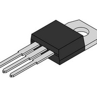
Schottky (Diodes & Rectifiers) 20A 100V H-Series

MBR20H100CT

Manufacturer Part Number
MBR20H100CT
Description
Schottky (Diodes & Rectifiers) 20A 100V H-Series
Manufacturer
ON Semiconductor
Series
SWITCHMODE™r
Datasheet

Specifications of MBR20H100CT

Product
Schottky Diodes
Peak Reverse Voltage
100 V
Forward Continuous Current
10 A
Max Surge Current
250 A
Configuration
Dual Common Cathode
Forward Voltage Drop
0.84 V @ 20 A
Maximum Reverse Leakage Current
4.5 uA
Operating Temperature Range
+ 175 C
Mounting Style
Through Hole
Package / Case
TO-220AB
Voltage - Forward (vf) (max) @ If
770mV @ 10A
Current - Reverse Leakage @ Vr
4.5µA @ 100V
Current - Average Rectified (io) (per Diode)
10A
Voltage - Dc Reverse (vr) (max)
100V
Reverse Recovery Time (trr)
-
Diode Type
Schottky
Speed
Fast Recovery =< 500ns, > 200mA (Io)
Diode Configuration
1 Pair Common Cathode
Mounting Type
Through Hole
Lead Free Status / RoHS Status
Lead free / RoHS Compliant

Available stocks

Company
Part Number
Manufacturer
Quantity
Price
Part Number:
MBR20H100CT
Manufacturer:
VISHAY0
Quantity:
49
Part Number:
MBR20H100CT
Manufacturer:
ON
Quantity:
12 500
Part Number:
MBR20H100CT
Manufacturer:
ST
0
Part Number:
MBR20H100CT
Manufacturer:
ON/安森美
Quantity:
20 000
Part Number:
MBR20H100CT-E1
Manufacturer:
SAM
Quantity:
1
Part Number:
MBR20H100CT-E1
Manufacturer:
BCD
Quantity:
20 000
Part Number:
MBR20H100CT-E3/45
Manufacturer:
Vishay Semiconductors
Quantity:
135
Part Number:
MBR20H100CTF-E1
Manufacturer:
BCD
Quantity:
4 250
Part Number:
MBR20H100CTG
Manufacturer:
ON/安森美
Quantity:
20 000
Company:
Part Number:
MBR20H100CTG
Quantity:
500
Part Number:
MBR20H100CTG-E3/45
Manufacturer:
VISHAY/威世
Quantity:
20 000
Company:
Part Number:
MBR20H100CTG-E3/45
Quantity:
70 000
MBR20H100CT,
MBRB20H100CT,
MBRF20H100CT
SWITCHMODE]
Power Rectifier
100 V, 20 A
Features and Benefits
Applications
Mechanical Characteristics:
MAXIMUM RATINGS
© Semiconductor Components Industries, LLC, 2010
January, 2010 − Rev. 8
Please See the Table on the Following Page
1.9 Grams (TO−220)
1.7 Grams (D
Leads are Readily Solderable
260°C Max. for 10 Seconds
Low Forward Voltage: 0.64 V @ 125°C
Low Power Loss/High Efficiency
High Surge Capacity
175°C Operating Junction Temperature
20 A Total (10 A Per Diode Leg)
Guard−Ring for Stress Protection
Pb−Free Packages are Available
Power Supply − Output Rectification
Power Management
Instrumentation
Case: Epoxy, Molded
Epoxy Meets UL 94 V−0 @ 0.125 in
Weight (Approximately):
Finish: All External Surfaces Corrosion Resistant and Terminal
Lead Temperature for Soldering Purposes:
2
PAK)
1
See detailed ordering and shipping information in the package
dimensions section on page 2 of this data sheet.
1
1
1
2
2
2
20 AMPERES, 100 VOLTS
3
3
3
SCHOTTKY BARRIER
ORDERING INFORMATION
A
Y
WW
B20H100 = Device Code
G
AKA
4
ISOLATED TO−220
http://onsemi.com
1
3
4
RECTIFIER
CASE 221D
CASE 221A
TO−220AB
STYLE 3
STYLE 6
CASE 418B
= Assembly Location
= Year
= Work Week
= Pb−Free Device
= Polarity Designator
STYLE 3
D
2
PAK
Publication Order Number:
MBR20H100CT/D
2, 4
DIAGRAMS
MARKING
B20H100G
B20H100G
B20H100G
AYWW
AYWW
AYWW
AKA
AKA
AKA

Related parts for MBR20H100CT

MBR20H100CT Summary of contents

Page 1

... B20H100 = Device Code G = Pb−Free Device AKA = Polarity Designator ORDERING INFORMATION See detailed ordering and shipping information in the package dimensions section on page 2 of this data sheet MARKING DIAGRAMS AYWW B20H100G AKA AYWW B20H100G AKA AYWW B20H100G PAK AKA Publication Order Number: MBR20H100CT/D ...

Page 2

... Operating Junction Temperature (Note 1) Storage Temperature Voltage Rate of Change (Rated Controlled Avalanche Energy (see test conditions in Figures 11 and 12) ESD Ratings: Machine Model = C Human Body Model = 3B THERMAL CHARACTERISTICS Maximum Thermal Resistance (MBR20H100CT and MBRB20H100CT) (MBRF20H100CT) ELECTRICAL CHARACTERISTICS Maximum Instantaneous Forward Voltage (Note 25° 125° ...

Page 3

T = 150° 125° 25° 0.1 0 0.2 0.4 0 INSTANTANEOUS FORWARD VOLTAGE (VOLTS) F Figure 1. Typical Forward Voltage 1.0E−01 1.0E− 150°C J 1.0E−03 T ...

Page 4

... Figure 8. Thermal Response Junction−to−Ambient for MBR20H100CT and MBRB20H100CT 0.5 1 0.2 0.1 0.05 0.1 0.01 SINGLE PULSE 0.01 0.000001 0.00001 0.0001 Figure 9. Thermal Response Junction−to−Case for MBR20H100CT and MBRB20H100CT T = 25° REVERSE VOLTAGE (VOLTS) R Figure 7. Capacitance 0.001 0.01 ...

Page 5

D = 0.5 1 0.2 0.1 0.05 0.1 0.01 0.01 SINGLE PULSE 0.001 0.000001 0.00001 0.0001 Figure 10. Thermal Response Junction−to−Case for MBRF20H100CT + COIL MERCURY SWITCH DUT S 1 Figure 11. ...

Page 6

... −T− SEATING PLANE 0.13 (0.005 VARIABLE CONFIGURATION ZONE VIEW W−W 1 *For additional information on our Pb−Free strategy and soldering details, please download the ON Semiconductor Soldering and Mounting Techniques Reference Manual, SOLDERRM/D. PACKAGE DIMENSIONS 2 D PAK 3 CASE 418B−04 ISSUE VIEW W− ...

Page 7

... BSC 5.08 BSC Q 0.122 0.138 3.10 3.50 R 0.099 0.117 2.51 2.96 S 0.092 0.113 2.34 2.87 U 0.239 0.271 6.06 6.88 STYLE 3: PIN 1. ANODE 2. CATHODE 3. ANODE ON Semiconductor Website: www.onsemi.com Order Literature: http://www.onsemi.com/orderlit For additional information, please contact your local Sales Representative MBR20H100CT/D ...

Related keywords