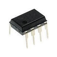
TISP61512P-S Bourns Inc., TISP61512P-S Datasheet - Page 7

TISP61512P-S
Manufacturer Part Number
TISP61512P-S
Description
Sidacs
Manufacturer
Bourns Inc.
Datasheet
1.TISP61512P-S.pdf
(9 pages)
Specifications of TISP61512P-S
Breakover Current Ibo Max
5 A
Rated Repetitive Off-state Voltage Vdrm
100 V
Off-state Leakage Current @ Vdrm Idrm
0.005 mA
Forward Voltage Drop
4 V
Mounting Style
Through Hole
Package / Case
PDIP-8
Lead Free Status / RoHS Status
Lead free / RoHS Compliant
The electrical characteristics of a thyristor overvoltage protector are strongly dependent on junction temperature, T
value will depend on the junction temperature at the instant of measurement. The values given in this data sheet were measured on commercial
testers, which generally minimize the temperature rise caused by testing.
Figure 3 shows a typical TISP61511D SLIC card protection circuit. The incoming line wires, R and T, connect to the relay matrix via the series
overcurrent protection. Fusible resistors, fuses and positive temperature coefficient (PTC) resistors can be used for overcurrent protection.
Resistors will reduce the prospective current from the surge generator for both the TISP61511D and the ring/test protector. The TISP7xxxF3
protector has the same protection voltage for any terminal pair. This protector is used when the ring generator configuration may be ground or
battery-backed. For dedicated ground-backed ringing generators, the TISP3xxxF3 gives better protection as its inter-wire protection voltage is
twice the wire to ground value.
Relay contacts 3a and 3b connect the line wires to the SLIC via the TISP61511D protector. The protector gate reference voltage comes from the
SLIC negative supply (V
Most lightning tests, used for equipment verification, specify a unidirectional sawtooth waveform which has an exponential rise and an
exponential decay. Wave shapes are classified in terms of Peak Amplitude (voltage or current), rise time and a decay time to 50 % of the
maximum amplitude. The notation used for the wave shape is amplitude, rise time/decay time . A 38 A, 5/310 µs wave shape would have a
peak current value of 38 A, a rise time of 5 µs and a decay time of 310 µs.
There are three categories of surge generator type; single wave shape, combination wave shape and circuit defined. Single wave shape
generators have essentially the same waveshape for the open circuit voltage and short circuit current (e.g. 10/1000 µs open circuit voltage
and short circuit current). Combination generators have two wave shapes, one for the open circuit voltage and the other for the short circuit
current (e.g. 1.2/50 µs open circuit voltage and 8/20 µs short circuit current). Circuit specified generators usually equate to a combination
generator, although typically only the open circuit voltage waveshape is referenced (e.g. a 10/700 µs open circuit voltage generator typically
produces a 5/310 µs short circuit current). If the combination or circuit defined generators operate into a finite resistance the wave shape
produced is intermediate between the open circuit and short circuit values.
JULY 1995 — REVISED JULY 2008
Specifications are subject to change without notice.
Customers should verify actual device performance in their specific applications.
Electrical Characteristics
Application Circuit
Impulse Conditions
WIRE
RING
WIRE
TIP
TISP61511D Gated Protectors
PROTECTION
CURRENT
OVER-
R1a
R1b
BAT
). A 220 nF gate capacitor sources the high gate current pulses caused by fast rising impulses.
Th3
PROTECTION
RING/TEST
3xxxF3
7xxxF3
TISP
OR
Th2
Th1
Figure 3. Typical Application Circuit
APPLICATIONS INFORMATION
EQUIP-
RELAY
S1a
MENT
TEST
TEST
S1b
GENERATOR
S2b
RING
RELAY
RING
S2a
RELAY
SLIC
S3b
S3a
PROTECTOR
61511D
220 nF
SLIC
TISP
J
Th4
Th5
. Hence a characteristic
V
SLIC
AI6XAA
BAT


