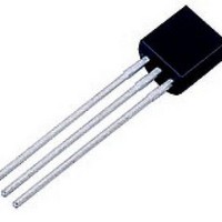
MCR100-006 ON Semiconductor, MCR100-006 Datasheet - Page 6

MCR100-006
Manufacturer Part Number
MCR100-006
Description
SCRs 400V 800mA
Manufacturer
ON Semiconductor
Datasheet
1.MCR100-6ZL1.pdf
(7 pages)
Specifications of MCR100-006
Breakover Current Ibo Max
10 A
Rated Repetitive Off-state Voltage Vdrm
400 V
Off-state Leakage Current @ Vdrm Idrm
0.01 mA
Forward Voltage Drop
1.7 V
Gate Trigger Voltage (vgt)
0.8 V
Maximum Gate Peak Inverse Voltage
5 V
Gate Trigger Current (igt)
0.2 mA
Holding Current (ih Max)
5 mA
Mounting Style
Through Hole
Package / Case
TO-92-3 (TO-226)
Lead Free Status / RoHS Status
Lead free / RoHS Compliant
Available stocks
Company
Part Number
Manufacturer
Quantity
Price
NOTES:
1. Maximum alignment deviation between leads not to be greater than 0.2 mm.
2. Defective components shall be clipped from the carrier tape such that the remaining protrusion (L) does not exceed a maximum of 11 mm.
3. Component lead to tape adhesion must meet the pull test requirements.
4. Maximum non−cumulative variation between tape feed holes shall not exceed 1 mm in 20 pitches.
5. Hold down tape not to extend beyond the edge(s) of carrier tape and there shall be no exposure of adhesive.
6. No more than 1 consecutive missing component is permitted.
7. A tape trailer and leader, having at least three feed holes is required before the first and after the last component.
8. Splices will not interfere with the sprocket feed holes.
Symbol
F1, F2
H2A
H2B
W1
W2
D2
H1
H4
H5
P1
P2
T1
T2
L1
W
D
H
P
T
L
Tape Feedhole Diameter
Component Lead Thickness Dimension
Component Lead Pitch
Bottom of Component to Seating Plane
Feedhole Location
Deflection Left or Right
Deflection Front or Rear
Feedhole to Bottom of Component
Feedhole to Seating Plane
Defective Unit Clipped Dimension
Lead Wire Enclosure
Feedhole Pitch
Feedhole Center to Center Lead
First Lead Spacing Dimension
Adhesive Tape Thickness
Overall Taped Package Thickness
Carrier Strip Thickness
Carrier Strip Width
Adhesive Tape Width
Adhesive Tape Position
H4 H5
H
TO−92 EIA RADIAL TAPE IN BOX OR ON REEL
H2A
P2
P1
Figure 7. Device Positioning on Tape
F1
P
F2
Item
H2A
P2
http://onsemi.com
6
L
D
W2
L1
H1
W1
W
0.09842
0.1496
0.0945
0.3346
0.7086
0.3346
0.4921
0.2342
0.1397
0.6889
0.2165
0.015
0.610
0.014
.0059
Min
.059
0.06
—
0
0
T1
Inches
T
H2B
0.01968
0.1653
0.3741
0.5079
0.2658
0.1556
0.0567
0.7481
0.2841
0.020
0.110
0.039
0.051
0.768
0.649
0.433
0.027
Max
.156
0.08
Specification
—
H2B
T2
Min
0.38
15.5
12.5
5.95
3.55
0.15
0.35
17.5
3.8
2.4
1.5
8.5
8.5
2.5
5.5
.15
18
—
0
0
Millimeter
Max
0.51
19.5
16.5
12.9
6.75
3.95
0.20
1.44
0.65
4.2
2.8
4.0
9.5
1.0
1.0
6.3
0.5
11
19
—


