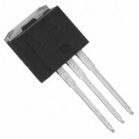
MBR4045CT-1PBF Vishay, MBR4045CT-1PBF Datasheet

MBR4045CT-1PBF
Specifications of MBR4045CT-1PBF
VS-MBR4045CT-1PBF
VS-MBR4045CT-1PBF
VSMBR4045CT-1PBF
VSMBR4045CT-1PBF
Related parts for MBR4045CT-1PBF
MBR4045CT-1PBF Summary of contents
Page 1
... High frequency operation V Guard ring for enhanced ruggedness and long term °C reliability Case Styles MBRB4045CT Base Common Cathode Common 3 Anode Cathode Anode 2 D PAK 40 Amp MBR4045CT-1 Base Common Cathode Common 3 Anode Cathode Anode TO-262 1 ...
Page 2
... MBR4045CT, MBRB4045CT, MBR4045CT-1 PreBulletin PD-20051 rev. A 09/01 Voltage Ratings Parameters V Max. DC Reverse Voltage ( Max. Working Peak Reverse Voltage (V) RWM Absolute Maximum Ratings Parameters I Max. Average Forward (Per Leg) F(AV) Current (Per Device) I Peak Repetitive Forward FRM Current (Per Leg) I Max.Peak One Cycle Non -Repetitive ...
Page 3
... Fig Max. Forward Voltage Drop Characteristics (Per Leg 0.20 0.1 (Thermal Resistance) 0.01 0.001 0.00001 0.0001 Fig Max. Thermal Impedance Z www.irf.com MBR4045CT, MBRB4045CT, MBR4045CT-1 1000 100 10 1 0.1 0.01 0.001 150˚C J Fig Typical Values Of Reverse Current T = 125˚C J 900 T = 25˚C J ...
Page 4
... MBR4045CT, MBRB4045CT, MBR4045CT-1 PreBulletin PD-20051 rev. A 09/01 160 DC 140 120 Square Wave (D = 0.50) Rated Vr Applied 100 see note ( Average Forward Current - I Fig Max. Allowable Case Temperature Vs. Average Forward Current 1000 100 10 Square Wave Pulse Duration - t Fig Max. Non-Repetitive Surge Current (Per Leg) ...
Page 5
... Common 3 Cathode Anode Anode 2 Conform to JEDEC outline D Pak (SMD-220) Dimensions in millimeters and (inches) www.irf.com MBR4045CT, MBRB4045CT, MBR4045CT-1 1.32 (0.05) 3.78 (0.15) 1.22 (0.05) DIA. 3.54 (0.14) 6.48 (0.25) 2.92 (0.11) 6.23 (0.24) 2.54 (0.10) 2° 3.96 (0.16) 0.10 (0.004) 3.55 (0.14) 2 ...
Page 6
... MBR4045CT, MBRB4045CT, MBR4045CT-1 PreBulletin PD-20051 rev. A 09/01 Outline Table Modified JEDEC outline TO-262 Dimensions in millimeters and (inches) Marking Information EXAMPLE: THIS IS AN MBRB4045CT 6 (K) INTERNATIONAL RECTIFIER LOGO MBRB4045CT 9912 9G3A ASSEMBLY LOT CODE (A) (A) Base Common Cathode Common 3 Cathode Anode Anode ...
Page 7
... DIA. 360 (14.173) DIA. MAX. Ordering Information Table Device Code MBR www.irf.com MBR4045CT, MBRB4045CT, MBR4045CT-1 1.60 (0.063) 1.50 (0.059) 1.60 (0.063) 4.10 (0.161) DIA. 1.50 (0.059) 3.90 (0.153) 11.60 (0.457) 11.40 (0.449) 1.75 (0.069) DIA. 10.90 (0.429) 1.25 (0.049) 10 ...
Page 8
... IBV=0.267178064395486A,RS= 0.000581298,CJO=2.94926944579954E-08, + VJ=0.779269989906853,XTI=2, EG=0.730300626417364) ******************************************** *Implementation of VCG2T CAT TRES 1E-6 .MODEL TRES RES(R=1,TC1=19.7716341798827) GP1 ANO CAT VALUE={-ABS(I(VX))*(EXP((((-2.531689E-03/19.77164)*((V(2,CAT)*1E6)/ (I(VX)+1E-6)-1))+1)*6.454822E-02*ABS(V(ANO,CAT)))-1)} ******************************************** .ENDS MBR4045CT Thermal Model Subcircuit .SUBCKT MBR4045CT 5 1 CTHERM1 5 4 1.84E+00 CTHERM2 4 3 1.74E+01 CTHERM3 3 2 9.36E+01 ...


