SBR40U120CT Diodes Inc, SBR40U120CT Datasheet
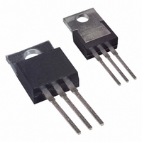
SBR40U120CT
Specifications of SBR40U120CT
Available stocks


Related parts for SBR40U120CT


SBR40U120CT Summary of contents
Page 1
... O (Total) I FSM Symbol R θ STG @T = 25°C unless otherwise specified A Symbol Min Typ - - www.diodes.com SBR40U120CT 40A SBR SUPER BARRIER RECTIFIER Value Unit 120 20 40 300 Value Unit 2.0 ºC/W -65 to +150 Max Unit Test Condition 0. 20A 25º 0. 20A 125º 120V 25º ...
Page 2
... Part Number SBR40U120CT SBR40U120CT-G Notes: 4. For packaging details our website at http://www.diodes.com/datasheets/ap02007.pdf. 5. For Green Molding Compound version part numbers, add "-G" suffix to part number above. Examples: SBR40U120CT-G. Marking Information SBR is a registered trademark of Diodes Incorporated. SBR40U120CT Document number: DS31584 Rev ...
Page 3
... D 14. 9.66 H1 5.85 L 12. 3.54 Q 2.54 All Dimensions in mm IMPORTANT NOTICE LIFE SUPPORT www.diodes.com SBR40U120CT Typ Max - 4.82 - 1.39 - 2.92 - 0.61 - 16.51 - 9.01 2.54 5.08 - 10.66 - 6.85 - 14. 6.35 - 4.08 - 3.42 © Diodes Incorporated ...