BAV199 Diodes Inc, BAV199 Datasheet
BAV199
Specifications of BAV199
BAV199DITR
Available stocks


Related parts for BAV199


BAV199 Summary of contents
Page 1
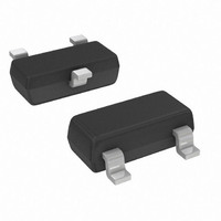
... Symbol θ STG = 25°C unless otherwise specified A Symbol Min 85 V (BR)R ⎯ ⎯ ⎯ ⎯ www.diodes.com BAV199 TOP VIEW Value Unit 160 mA 140 500 mA 4.0 1.0 A 0.5 Value Unit 250 mW °C/W 500 °C -65 to +150 Typ Max Unit Test Condition ⎯ ...
Page 2
... Single diode loaded Double diode loaded 0 50 100 150 ° AMBIENT TEMPERATURE ( C) A Fig. 4 Current Derating Curve, Per Element Packaging 3000/Tape & Reel 2008 2009 2010 2011 Jul Aug Sep Oct Nov © Diodes Incorporated BAV199 2 200 2012 Z Dec D May 2008 ...
Page 3
... Diodes Incorporated products are not authorized for use as critical components in life support devices or systems without the expressed written approval of the President of Diodes Incorporated. BAV199 Document number: DS30232 Rev Dimensions Value (in mm IMPORTANT NOTICE LIFE SUPPORT www.diodes.com BAV199 SOT-23 Dim Min Max A 0.37 0.51 B 1.20 1. ...