861SSRA208-DC-2 Magnecraft / Schneider Electric, 861SSRA208-DC-2 Datasheet - Page 28
861SSRA208-DC-2
Manufacturer Part Number
861SSRA208-DC-2
Description
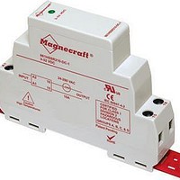
Modular Style
Manufacturer
Magnecraft / Schneider Electric
Datasheet
1.70S2-01-A-05-N.pdf
(32 pages)
Specifications of 861SSRA208-DC-2
Control Voltage Range
3 VDC to 32 VDC
Load Voltage Rating
24 VAC to 280 VAC
Load Current Rating
8 A
Contact Form
SPST - NO
Mounting Style
DIN Rail
Lead Free Status / RoHS Status
Lead free / RoHS Compliant
Lead Free Status / RoHS Status
Lead free / RoHS Compliant


Magnecraft
Solid State Relays
Application Data
®
(continued)
Load Considerations
The major cause of application problems with SSRs is improper heat sinking�
Following that are issues which result from operating conditions which specific loads
impose upon an SSR� Carefully considered the surge characteristics of the load
when designing an SSR as a switching solution�
• Resistive Loads
Loads of constant value of resistance are the simplest application of SSRs� Proper
thermal consideration along with attention to the steady state current ratings is
important for reliable operation�
• DC Loads
DC loads are inductive loads� Place a diode across the load to absorb surges
during turn off�
• Lamp Loads
Incandescent lamp loads, though basically resistive, require special consideration�
Because the resistance of the cold filament is about 5 to 10 percent of the heated
value, a large inrush current can occur� It is essential to verify that this inrush
current is within the surge specifications of the SSR� One must also check that the
lamp rating of the SSR is not exceeded� This is a UL rating based on the inrush of
a typical lamp� Due to the unusually low filament resistance at the time of turn-on, a
zero voltage turn on characteristic is particularly desirable with incandescent lamps�
• Capacitive Loads
These types of loads can be difficult because of their initial appearance as short
circuits� High surge currents can occur while charging, limited only by circuit
resistance� Use caution with low impedance capacitive loads to verify that the dl/dt
capabilities are not exceeded� Zero voltage turn on is a particularly valuable means
of limiting dl/dt with capacitive loads�
• Motors and Solenoids
Motor and solenoid loads require special attention for reliable SSR functionality�
Solenoids have high initial surge currents because their stationary impedance is
very low� Motors also frequently have severe inrush currents during starting and can
impose unusually high voltages during turn off� As a motor’s rotor rotates, it creates
a back EMF that reduces the flow of current� This back EMF can add to the applied
line voltage and create an over voltage condition during turn off� Likewise, verify that
the inrush currents associated with mechanical loads having high starting torque
or inertia, such as fans and flywheels, are within the surge capabilities of the SSR�
Use a current shunt and oscilloscope to examine the duration of the inrush current�
28
Related parts for 861SSRA208-DC-2
Image
Part Number
Description
Manufacturer
Datasheet
Request
R

Part Number:
Description:
Solid State Relays 3A/50VAC SPST-NO
Manufacturer:
Magnecraft / Schneider Electric
Datasheet:

Part Number:
Description:
HEAT SINK MAGNECRAFT
Manufacturer:
Magnecraft / Schneider Electric
Datasheet:

Part Number:
Description:
Bracket, Panel Mounting; Use with 711, 712, TDRSRX/SOX Series Magnecraft Relays
Manufacturer:
Magnecraft/Schneider Electric
Datasheet:
Part Number:
Description:
Bracket, DIN Rail Mounting; Use with 711, 712, TDRSRX/SOX Series Magnecraft Relays
Manufacturer:
Magnecraft/Schneider Electric
Datasheet:

Part Number:
Description:
Solid State Relays SPST-NO 48 to 480 VAC
Manufacturer:
Magnecraft / Schneider Electric
Datasheet:
Part Number:
Description:
Solid State Relays SPST-NO 48 to 480 VAC
Manufacturer:
Magnecraft / Schneider Electric
Datasheet:
Part Number:
Description:
Solid State Relays SPST-NO 3 to 50 VDC
Manufacturer:
Magnecraft / Schneider Electric
Datasheet:
Part Number:
Description:
Solid State Relays SPST-NO 48 to 600 VAC
Manufacturer:
Magnecraft / Schneider Electric
Datasheet:
Part Number:
Description:
Solid State Relays SPST-NO 3 to 150 VDC
Manufacturer:
Magnecraft / Schneider Electric
Datasheet:
Part Number:
Description:
Solid State Relays SPST-NO 48 to 600 VAC
Manufacturer:
Magnecraft / Schneider Electric
Datasheet:
Part Number:
Description:
Solid State Relays SPST-NO 24 to 280 VAC
Manufacturer:
Magnecraft / Schneider Electric
Datasheet:

Part Number:
Description:
Solid State Relays 5V/240V PC TERMINAL
Manufacturer:
Magnecraft / Schneider Electric

Part Number:
Description:
Solid State Relays SPST-NO 8 A 3.5-32 VDC
Manufacturer:
Magnecraft / Schneider Electric
Datasheet:
Part Number:
Description:
Solid State Relays SPST-NO 24 to 280 VAC
Manufacturer:
Magnecraft / Schneider Electric
Datasheet:
Part Number:
Description:
Relay; E-Mech; Power; On Delay; SPDT; Cur-Rtg 15A; Ctrl-V 120AC; Vol-Rtg 240/24AC/DC
Manufacturer:
Magnecraft/Schneider Electric
Datasheet: