EE-SX473 Omron, EE-SX473 Datasheet - Page 5
EE-SX473
Manufacturer Part Number
EE-SX473
Description
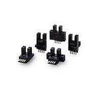
5mm SLOT PMS L-ON NPN C MOUNT
Manufacturer
Omron
Specifications of EE-SX473
Sensing Distance
0.197" (5mm)
Sensing Method
Transmissive
Output Configuration
NPN - Open Collector/Light-ON
Mounting Type
Chassis Mount
Current - Supply
35mA
Voltage - Supply
5 V ~ 24 V
Package / Case
Module, Connector
Output Current
100mA
Sensor Output
NPN Open Collector
Supply Voltage Range Dc
5V To 24V
Rohs Compliant
Yes
Lead Free Status / RoHS Status
Lead free / RoHS Compliant
Response Time
-
Lead Free Status / Rohs Status
Lead free / RoHS Compliant
Other names
EESX473
Available stocks
Company
Part Number
Manufacturer
Quantity
Price
Company:

Part Number:
EE-SX473
Manufacturer:
OMRON
Quantity:
1 000
Company:
Part Number:
EE-SX473
Manufacturer:
AH
Quantity:
8 690
Company:
Part Number:
EE-SX473P
Manufacturer:
OMRON
Quantity:
1 000


PNP Output
*1. Do not connect the L terminal to 0 V when using dark-ON operation.
Safety Precautions
Refer to Warranty and Limitations of Liability.
This product is not designed or rated for ensuring
safety of persons either directly or indirectly.
Do not use it for such purposes.
● Operating Environment
These Photomicrosensors have an IP50 (conforms to IEC) enclosure
and do not have a water-proof or dust-proof structure. Therefore, do
not use them in applications in which the sensor will be subjected to
splashes from water, oil, or any other liquid. Liquid entering the
Sensor may result in malfunction.
EE-SX67@P
EE-SX67@P-WR
EE-SX67@P-CJ1-R
EE-SX670R
EE-SX671R
EE-SX672R
EE-SX673R
EE-SX674R
EE-SX470P
EE-SX471P
EE-SX472P
EE-SX473P
EE-SX474P
Model
Precautions for Safe Use
configuration
Light-ON
Dark-ON
Light-ON
Dark-ON
Light-ON
Output
WARNING
Light indicator
(red)
Output
transistor
Load
(relay)
Light indicator
(red)
Output
transistor
Load
(e.g., relay)
Light indicator
(red)
Output
transistor
Load
(e.g., relay)
Light indicator
(red)
Output
transistor
Load
(relay)
Light indicator
(red)
Output
transistor
Load
(relay)
Timing charts
Interrupted
Interrupted
Interrupted
Interrupted
Interrupted
Releases
Operates
Releases
Operates
Releases
Releases
Operates
Releases
Operates
Operates
Incident
Incident
Incident
Incident
Incident
OFF
OFF
OFF
OFF
OFF
OFF
OFF
OFF
OFF
OFF
ON
ON
ON
ON
ON
ON
ON
ON
ON
ON
positive
positive
positive
positive
Open between
Open between
Short-circuited
L
L
Short-circuited
L
L
connections
Terminal
terminal and
terminal and
terminal and
terminal and
between
between
Make sure that this product is used within the rated ambient
environment conditions.
● Installation
● Lot Number and Model Number Legend
• When direct soldering to the terminals, use the following guidelines.
Soldering
• The terminal base uses a polycarbonate resin, which could be
deformed by excessive soldering heat, resulting in damage to the
product's functionality.
*1
*1
---
Soldering Conditions
Item
iron
terminal
terminal
terminal
terminal
Temper-
350°C
ature
max.
Precautions for Correct Use
*The terminal arrangement depends on the model.
Check the dimensional diagrams.
Permissible
Light indicator
(red)
Light indicator (red)
3 s max.
time
circuit
circuit
Main
Main
The portion between the base of the
terminals and the position 1.5 mm from
the terminal base must not be soldered.
Output circuit
EE-SX47/67
OUT
OUT
L
*
Remarks
IC
IC
Load
Load
5 to
24 VDC
5 to
24 VDC
5
Related parts for EE-SX473
Image
Part Number
Description
Manufacturer
Datasheet
Request
R

Part Number:
Description:
PHOTOMICROSENSOR, TRANSISTOR
Manufacturer:
Omron
Datasheet:

Part Number:
Description:
PHOTO MICROSENSOR
Manufacturer:
Omron
Datasheet:

Part Number:
Description:
OPTO SENSOR 8MM WIDE SLOT TYPE
Manufacturer:
Omron
Datasheet:

Part Number:
Description:
OPTO SENSOR SLOT TYPE 5MM
Manufacturer:
Omron
Datasheet:

Part Number:
Description:
OPTO SENSOR SLOT TYPE 5MM
Manufacturer:
Omron
Datasheet:

Part Number:
Description:
PHOTO MICROSENSOR
Manufacturer:
Omron
Datasheet:

Part Number:
Description:
PHOTO MICROSENSOR :
Manufacturer:
Omron
Datasheet:
Part Number:
Description:
PHOTO MICROSENSOR
Manufacturer:
Omron
Datasheet:

Part Number:
Description:
Detector Connector For EE-SPW
Manufacturer:
Omron
Datasheet:

Part Number:
Description:
PHOTO MICROSENSOR
Manufacturer:
Omron
Datasheet:

Part Number:
Description:
PHOTO MICROSENSOR
Manufacturer:
Omron
Datasheet:

Part Number:
Description:
PHOTO MICROSENSOR
Manufacturer:
Omron
Datasheet:
Part Number:
Description:
Emitter Connector
Manufacturer:
Omron
Datasheet: