BYT28F-400-E3/45 Vishay, BYT28F-400-E3/45 Datasheet

DIODE DUAL 10A 400V TO-263AB

BYT28F-400-E3/45

Manufacturer Part Number
BYT28F-400-E3/45
Description
DIODE DUAL 10A 400V TO-263AB
Manufacturer
Vishay
Datasheets

Specifications of BYT28F-400-E3/45

Voltage - Forward (vf) (max) @ If
1.3V @ 5A
Current - Reverse Leakage @ Vr
10µA @ 400V
Current - Average Rectified (io) (per Diode)
5A
Voltage - Dc Reverse (vr) (max)
400V
Reverse Recovery Time (trr)
50ns
Diode Type
Standard
Speed
Fast Recovery =< 500ns, > 200mA (Io)
Diode Configuration
1 Pair Common Cathode
Mounting Type
Through Hole
Package / Case
TO-220-3 (Straight Leads, Isolated), ITO-220AB
Product
Ultra Fast Recovery Rectifier
Configuration
Dual Common Cathode
Reverse Voltage
400 V
Forward Voltage Drop
1.4 V
Recovery Time
50 ns
Forward Continuous Current
10 A
Max Surge Current
60 A
Reverse Current Ir
10 uA
Mounting Style
Through Hole
Maximum Operating Temperature
+ 150 C
Minimum Operating Temperature
- 40 C
Lead Free Status / RoHS Status
Lead free / RoHS Compliant
Document Number: 88552
Revision: 06-Nov-07
PRIMARY CHARACTERISTICS
MAXIMUM RATINGS (T
PARAMETER
Maximum repetitive peak reverse voltage
Maximum working reverse voltage
Maximum RMS voltage
Maximum DC blocking voltage
Maximum average forward rectified current at T
Peak forward surge current 8.3 ms single half sine-wave
superimposed on rated load per diode
Operating junction and storage temperature range
Isolation voltage (ITO-220AB only)
from terminal to heatsink t = 1 min
BYT28, UG10 Series
PIN 1
PIN 3
TO-220AB
Dual Common-Cathode Ultrafast Soft Recovery Rectifier
T
V
I
J
I
F(AV)
FSM
RRM
V
t
max.
rr
F
PIN 2
CASE
BYT28B, UGB10 Series
PIN 2
PIN 1
UG(F,B)10FCT & UG(F,B)10GCT, BYT28(F,B)-300 & BYT28(F,B)-400
1
K
TO-263AB
2
3
1
C
HEATSINK
= 25 °C unless otherwise noted)
K
2
BYT28F, UGF10 Series
PIN 1
PIN 3
300 V, 400 V
ITO-220AB
5 A x 2
150 °C
1.05 V
35 ns
60 A
C
= 100 °C
PIN 2
1
total device
per diode
2
3
FEATURES
TYPICAL APPLICATIONS
For use in high frequency rectifier of switching mode
power supplies, inverters, freewheeling diodes,
dc-to-dc converters, and other power switching
application.
MECHANICAL DATA
Case: TO-220AB, ITO-220AB, TO-263AB
Epoxy meets UL 94V-0 flammability rating
Terminals: Matte tin plated leads, solderable per
J-STD-002B and JESD22-B102D
E3 suffix for commercial grade, meets JESD 201 class
1A whisker test, HE3 suffix for high reliability grade
(AEC Q101 qualified), meets JESD 201 class 2
whisker test
Polarity: As marked
Mounting Torque: 10 in-lbs maximum
• Glass passivated chip junction
• Ultrafast recovery time
• Low switching losses, high efficiency
• Low forward voltage drop
• High forward surge capability
• Meets MSL level 1, per J-STD-020C, LF maximum
• Solder dip 260 °C, 40 s (for TO-220AB and
• Component in accordance to RoHS 2002/95/EC
SYMBOL
peak of 245 °C (for TO-263AB package)
ITO-220AB package)
and WEEE 2002/96/EC
T
V
J
V
V
I
I
V
, T
V
F(AV)
FSM
RWM
RRM
RMS
DC
AC
STG
Vishay General Semiconductor
BYT28-300
UG10FCT
300
300
210
300
- 40 to + 150
1500
5.0
10
60
BYT28-400
UG10GCT
400
400
280
400
www.vishay.com
UNIT
°C
V
V
V
A
A
V
1

Related parts for BYT28F-400-E3/45

BYT28F-400-E3/45 Summary of contents

Page 1

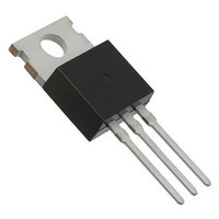
... UG(F,B)10FCT & UG(F,B)10GCT, BYT28(F,B)-300 & BYT28(F,B)-400 Dual Common-Cathode Ultrafast Soft Recovery Rectifier TO-220AB BYT28, UG10 Series BYT28F, UGF10 Series PIN 1 PIN 2 PIN 1 CASE PIN 3 PIN 3 TO-263AB BYT28B, UGB10 Series PIN 1 K PIN 2 HEATSINK PRIMARY CHARACTERISTICS I F(AV) V RRM I FSM t rr ...

Page 2

... I rr Note: (1) Pulse test: 300 µs pulse width duty cycle THERMAL CHARACTERISTICS (T PARAMETER Typical thermal resistance junction to case per diode ORDERING INFORMATION (Example) PACKAGE PREFERRED P/N TO-220AB BYT28-400-E3/45 ITO-220AB BYT28F-400-E3/45 TO-263AB BYT28B-400-E3/45 TO-263AB BYT28B-400-E3/81 (1) TO-220AB BYT28-400HE3/45 ITO-220AB BYT28F-400HE3/45 TO-263AB BYT28B-400HE3/45 TO-263AB ...

Page 3

... Figure 4. Typical Reverse Characteristics Per Diode 120 100 100 25 Figure 5. Reverse Switching Characteristics Per Diode 100 10 1 1.4 1.6 1.8 0.1 Figure 6. Typical Junction Capacitance Per Diode Vishay General Semiconductor T = 125 ° 100 ° ° 100 Percent of Rated Peak Reverse Voltage (%) A/µ A/µ A/µ 100 A/µ A/µ ...

Page 4

... UG(F,B)10FCT & UG(F,B)10GCT, BYT28(F,B)-300 & BYT28(F,B)-400 Vishay General Semiconductor PACKAGE OUTLINE DIMENSIONS in inches (millimeters) TO-220AB 0.415 (10.54) MAX. 0.370 (9.40) 0.154 (3.91) 0.360 (9.14) 0.148 (3.74) 0.113 (2.87) 0.103 (2.62) 0.145 (3.68) 0.135 (3.43) 0.635 (16.13) 0.625 (15.87) PIN ...

Page 5

... Information contained herein is intended to provide a product description only. No license, express or implied, by estoppel or otherwise, to any intellectual property rights is granted by this document. Except as provided in Vishay's terms and conditions of sale for such products, Vishay assumes no liability whatsoever, and disclaims any express or implied warranty, relating to sale and/or use of Vishay products including liability or warranties relating to fitness for a particular purpose, merchantability, or infringement of any patent, copyright, or other intellectual property right ...

Related keywords