P2CF-08 Omron, P2CF-08 Datasheet
P2CF-08
Specifications of P2CF-08
Z2407
Available stocks


Related parts for P2CF-08


P2CF-08 Summary of contents
Page 1
General-purpose Relays and Power Relays Sockets 238 General-purpose Relays and Power Relays Sockets ...
Page 2
Square Sockets Item P2RF (Track-mounting) *see page 246 Screw terminal 5 pins P2RF-05-E P2RF-05 Approx Approx pins P2RF-08 P2RF-08-E Approx Approx Note: @-E Models are of finger-protect construction. Round terminals cannot ...
Page 3
Item PYF (Track- mounting) *see page 250 Screw terminal Solder terminal 11 pins PYF11A PY11 Approx Approx PY11-Y1 14 pins PYF14A PY14 Approx Approx PY14-Y1 PYF14A-E PYF14A-N PY14-Y2 PYF14T Approx ...
Page 4
... Round Sockets Item PF P2CF (Track- (Track- mounting) mounting) *see page 258 8 pins PF083A P2CF-08 Approx Approx PF083A-E PF085A Approx pins PF113A P2CF-11 Approx Approx PF113A-E 14 pins --- --- 20 pins --- PF202 Approx. 170 g Note: This model succeeds the P3G-11 for which production was stopped in March 1991. ...
Page 5
Hold-down Clips For Square Sockets PYC-A1 PYC-A2 (see note) (see note) 5 max. 5 max. 36.3 42.8 4.5 4.5 1.2 4.5 1.2 4.5 PYC-P2 PYC 2.5 PYC 10 3.7 34.5 For Round Sockets PEC-A6 PFC-A1 (see ...
Page 6
Models Used with Sockets Group MY(K) MY2 MY3 MY4, MY2K LY LY1, LY2 LY3 LY4 G2A(K) G2A, G2A-434, G2AK MK(K) MK2P MK3P, MK2KP MM(K) MM2(X)P MM3P, MM2(X)KP MM3XP, MM3(X)KP, MM4(X)P, MM4(X)KP G4Q --- G7L G7L-@A-T(J) ■ Models Used with ...
Page 7
Socket Performance Characteristics Item Carry current P2RF-05(- P2RF-08(- P2R-057P 10 A P2R-087P 5 A P2R-05A 10 A P2R-08A 5 A P7TF- PYF08A PYF08A (see note 3) PYF11A 5 A ...
Page 8
... Item Carry current P7LF- PF@@@ P2CF 5 A P3G( 8PFA( 11PFA( PL@@(- PLE@@- P6D-04P 5 A P7S-14 Note: 1. The values given above are initial values. 2. The values for insulation resistance were measured at 500 V at the same place as the dielectric strength. 3. The maximum operating ambient temperature for the PYF08A-N and PYF14A When using the PYF08A-N or PYF14A operating ambient temperature exceeding 40 C, reduce the current to 60%. ■ ...
Page 9
Dimensions Note: All units are in millimeters unless otherwise indicated. ■ P2RF Dimensions P2RF-05 (One pole) Five, M3 71.5 max. 19.5 max. P2RF-05-E (One pole) M3.5 screw 3.5-dia. holes 85.5 max. * When mounted on H3RN-1@. P2RF-08 (Two ...
Page 10
Dimensions P2RF-08-E (Two poles) M3 screw 3.5-dia. holes 85.5 max. * When mounted on H3RN-2@. Note: When indicator modules with an I/O SSR are used, the No. 1 pin becomes positive. Terminal arrangement/ Internal connections (top view) 63 max. (84.9 ...
Page 11
P2R Dimensions P2R-05P (One pole) 14.5 max. 35.5 max. P2R-08P (Two poles) 14.5 max. 35.5 max. 36.5 max. P2R-057P (One pole) 14 max. 37 max. P2R-087P (Two poles) 14 max. 37 max. Note: When indicator modules with an I/O ...
Page 12
P2R/P7TF Dimensions P2R-05A (One pole) 14.5 max. 35.5 max. 36.5 max. P2R-08A (Two poles) 14.5 max. 35.5 max. P7TF-05 19 max. Screw with square washer 71.5 max. Note: When indicator modules with an I/O SSR are used, the No. ...
Page 13
PYF Dimensions Dimensions PYF08A Two, 4 mounting holes 72 max. 23 max. Two, 4 PYF08A-E mounting holes 6 72 max. 23 max. PYF08A-N 22 max ...
Page 14
Dimensions PYF14A Two, 4 mounting holes Fourteen sems 72 max. 29.5 max. PYF14A-E Two, 4 Fourteen, mounting holes sems 72 max. 29.5 max. PYF14A ...
Page 15
PY Dimensions Dimensions PY08 PY08-Y1 Eight, 3-dia. x 1.2 ellipses PY08- 2.7 42 max. 20 max. Note: PY08-Y1 includes the part outlined by the dashed lines above. PY08QN PY08QN2 PY08QN-Y1 PY08QN2- (20) 2 ...
Page 16
Dimensions PY14 PY14-Y1 (l=42 max.) PY14-Y3 (l=60 max.) Fourteen, 3-dia. x 1.2 ellipses * 20 max. l Note: PY14-Y1 includes the part outlined by the dashed lines above. PY14QN, PY14QN2 PY14QN-Y1 (l=42 max.) PY14QN2-Y1 (l=42 max.) PY14QN-Y2 (l=49 max.) PY14QN2-Y2 ...
Page 17
Dimensions PTF08A-E Two, 4 mounting holes 7 Eight, M3 sems 78.5 max. 28.5 max. PTF11A Two, 4 mounting holes 78.5 max. 37 max. PTF14A Two, 4 mounting holes 78.5 max. 45.5 max. ...
Page 18
PT Dimensions Dimensions PT08 PT08QN 5 0.3 9 25.5 29.5 max. max. 2.5 2.7 35 max. 2.7 Eight, 1.7-dia. x 3.5 ellipses 20.5 max. PT08 4.3 22 max. 18 max. *Keep a proper distance ...
Page 19
Dimensions PT14 PT14QN Fourteen, 1.7-dia. x 3.5 holes 42.5 max. 35 max. 26.5 max. 29.5 20.5 max. max. PT14-0 5* 26.5 max. 17.5 max. 29.5 max. *Keep a proper distance between the Socket and PCB patterns. Note: Use a panel ...
Page 20
P7S Dimensions Dimensions P7S-14F Fourteen, M3.0 40 max. 90.5 max. P7S-14A 61.5 max. 23 max. 33 max. P7S-14P 61.5 max. 23 max. Two, 6.5 dia. 7.9 29 max. Terminal arrangement/ Internal connections 47 max. 40 max. G7S-4A2B G7S-3A3B (bottom ...
Page 21
PF Dimensions Dimensions Eight, M3 PF083A sems screws 7 Two 4.2-dia. holes 52 max max. PF083A-E Eight, M3 sems Two, 4.2-dia. holes 52 max max. PF085A Eight, ...
Page 22
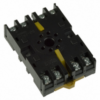
... PF202 101 max. Two, 4.5-dia. holes 71 max. Two, M3 Relay mounting screws Note: The key groove of PF083A and PF113A (used with MK Relays) are on the upside. ■ P2CF/PFA Dimensions Dimensions P2CF-08 Eight, M3.5 x 7.5 sems screws 70 max. Two, 4.5-dia. holes 50 max. P2CF-11 Eleven, M3.5 x 7.5 sems screws 70 max ...
Page 23
Dimensions 8PFA Eight, M3 sems screws Two, 4.5-dia. holes 81 max. 51 max. 8PFA1 Eight, M3 sems screws Two, 4.5-dia. holes 93 max. 51 max. ■ PFA/P3G/P3GA Dimensions Dimensions 11PFA Eleven, M3 sems screws ...
Page 24
Dimensions P3G-08 27 dia. P3GA-11 27 dia. ■ PL Dimensions Dimensions PL08 3.5 51 max max. PL08-Q 3.5 50.5 max max. PLE08-0 29 dia. 0.3 Note: When mounting, pay due attention to the direction of the ...
Page 25
PL Dimensions Dimensions PL11 30 dia. 51 max. 35 max. Approx. 20.5 max. PL11-Q 51 max. 35 max. 35 max. PLE11-0 29 0.1 dia. 22 max. PL15 66 max. 41 max. 45 max. 22 max. PL20 Two, 3.5-dia. holes ...
Page 26
... Omron Electronic Components, LLC Terms and Conditions of Sales I. GENERAL II. SALES III. PRECAUTIONS IV. WARRANTY AND LIMITATION V. INFORMATION; ETC. VI. MISCELLANEOUS ...
Page 27
... THE OMRON PRODUCT IS PROPERLY RATED AND INSTALLED FOR THE INTENDED USE WITHIN THE OVERALL EQUIPMENT OR SYSTEM. Complete “Terms and Conditions of Sale” for product purchase and use are on Omron’s website at http://www.components.omron.com – under the “About Us” tab, in the Legal Matters section. ...