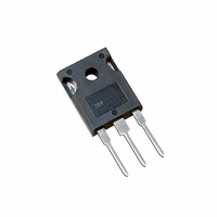
40CPQ080 Vishay, 40CPQ080 Datasheet - Page 2

40CPQ080
Manufacturer Part Number
40CPQ080
Description
DIODE SCHOTTKY 80V 20A TO-247AC
Manufacturer
Vishay
Datasheet
1.40CPQ100PBF.pdf
(6 pages)
Specifications of 40CPQ080
Voltage - Forward (vf) (max) @ If
910mV @ 40A
Current - Reverse Leakage @ Vr
1.25mA @ 80V
Current - Average Rectified (io) (per Diode)
20A
Voltage - Dc Reverse (vr) (max)
80V
Diode Type
Schottky
Speed
Fast Recovery =< 500ns, > 200mA (Io)
Diode Configuration
1 Pair Common Cathode
Mounting Type
Through Hole, Radial
Package / Case
TO-247-3 (Straight Leads), TO-247AC
Product
Schottky Rectifiers
Peak Reverse Voltage
80 V
Forward Continuous Current
40 A
Max Surge Current
2950 A
Configuration
Dual Common Cathode
Forward Voltage Drop
0.91 V
Maximum Reverse Leakage Current
1250 uA
Operating Temperature Range
- 55 C to + 175 C
Mounting Style
Through Hole
Lead Free Status / RoHS Status
Contains lead / RoHS non-compliant
Reverse Recovery Time (trr)
-
Lead Free Status / RoHS Status
Contains lead / RoHS non-compliant, Lead free / RoHS Compliant
Other names
*40CPQ080
VS-40CPQ080
VS-40CPQ080
VS40CPQ080
VS40CPQ080
VS-40CPQ080
VS-40CPQ080
VS40CPQ080
VS40CPQ080
Available stocks
Company
Part Number
Manufacturer
Quantity
Price
Company:
Part Number:
40CPQ080
Manufacturer:
IR
Quantity:
8 000
Part Number:
40CPQ080
Manufacturer:
IR
Quantity:
20 000
40CPQ080/40CPQ100
Vishay High Power Products
Note
(1)
www.vishay.com
2
ELECTRICAL SPECIFICATIONS
PARAMETER
Maximum forward voltage drop per leg
See fig. 1
Maximum reverse leakage current per leg
See fig. 2
Maximum junction capacitance per leg
Typical series inductance per leg
Maximum voltage rate of change
THERMAL - MECHANICAL SPECIFICATIONS
PARAMETER
Maximum junction and storage
temperature range
Maximum thermal resistance,
junction to case per leg
Maximum thermal resistance,
junction to case per package
Typical thermal resistance,
case to heatsink
Approximate weight
Mounting torque
Marking device
Pulse width < 300 µs, duty cycle < 2 %
maximum
minimum
For technical questions, contact: diodes-tech@vishay.com
SYMBOL
SYMBOL
T
V
I
dV/dt
R
R
RM
J
FM
, T
C
L
thCS
thJC
S
Schottky Rectifier, 2 x 20 A
T
(1)
Stg
(1)
20 A
40 A
20 A
40 A
T
T
V
Measured lead to lead 5 mm from package body
Rated V
DC operation
See fig. 4
DC operation
Mounting surface, smooth and greased
Non-lubricated threads
Case style TO-247AC (JEDEC)
J
J
R
= 25 °C
= 125 °C
= 5 V
R
DC
(test signal range 100 kHz to 1 MHz) 25 °C
TEST CONDITIONS
TEST CONDITIONS
T
T
V
J
J
R
= 25 °C
= 125 °C
= Rated V
R
- 55 to 175
VALUES
VALUES
Document Number: 93338
12 (10)
10 000
1.25
0.63
0.24
0.21
6 (5)
0.77
0.91
0.61
0.75
1.25
600
7.5
15
6
Revision: 21-Aug-08
40CPQ080
40CPQ100
kgf ⋅ cm
(lbf ⋅ in)
UNITS
UNITS
°C/W
V/µs
mA
nH
oz.
pF
°C
V
g


