MBRB2060CTG ON Semiconductor, MBRB2060CTG Datasheet

DIODE SCHOTTKY 60V 10A D2PAK

MBRB2060CTG

Manufacturer Part Number
MBRB2060CTG
Description
DIODE SCHOTTKY 60V 10A D2PAK
Manufacturer
ON Semiconductor
Series
SWITCHMODE™r
Datasheet

Specifications of MBRB2060CTG

Voltage - Forward (vf) (max) @ If
950mV @ 20A
Current - Reverse Leakage @ Vr
150µA @ 60V
Current - Average Rectified (io) (per Diode)
10A
Voltage - Dc Reverse (vr) (max)
60V
Diode Type
Schottky
Speed
Fast Recovery =< 500ns, > 200mA (Io)
Diode Configuration
1 Pair Common Cathode
Mounting Type
Surface Mount
Package / Case
D²Pak, TO-263 (2 leads + tab)
Product
Schottky Diodes
Peak Reverse Voltage
60 V
Forward Continuous Current
20 A
Max Surge Current
150 A
Configuration
Dual Common Cathode
Forward Voltage Drop
0.95 V
Maximum Reverse Leakage Current
150 uA
Operating Temperature Range
- 65 C to + 175 C
Mounting Style
SMD/SMT
Lead Free Status / RoHS Status
Lead free / RoHS Compliant
Reverse Recovery Time (trr)
-
Lead Free Status / Rohs Status
Lead free / RoHS Compliant
Other names
MBRB2060CTG
MBRB2060CTGOS

Available stocks

Company
Part Number
Manufacturer
Quantity
Price
Part Number:
MBRB2060CTG
Manufacturer:
ON
Quantity:
12 500
MBRB2060CT, MBR2060CT
SWITCHMODEt
Power Rectifiers
TO−220/D
Package
Barrier principle with a platinum barrier metal.
Features
Mechanical Characteristics:
Stresses exceeding Maximum Ratings may damage the device. Maximum
Ratings are stress ratings only. Functional operation above the Recommended
Operating Conditions is not implied. Extended exposure to stresses above the
Recommended Operating Conditions may affect device reliability.
1. The heat generated must be less than the thermal conductivity from
MAXIMUM RATINGS
© Semiconductor Components Industries, LLC, 2009
September, 2009 − Rev. 8
Peak Repetitive Reverse Voltage
Working Peak Reverse Voltage
DC Blocking Voltage
Average Rectified Forward Current
(Rated V
Peak Repetitive Forward Current
(Rated V
20 kHz, T
Non−Repetitive Peak Surge Current
(Surge Applied at Rated Load Conditions
Halfwave, Single Phase, 60 Hz)
Peak Repetitive Reverse Surge Current
(2.0 ms, 1.0 kHz)
Storage Temperature Range
Operating Junction Temperature (Note 1)
Voltage Rate of Change (Rated V
These state−of−the−art devices employ the use of the Schottky
1.9 Grams (Approximately) − TO−220
Leads are Readily Solderable
260°C Max. for 10 Seconds (D
Package Designed for Power Surface Mount Applications (D
Center−Tap Configuration (D
Guardring for Stress Protection
Low Forward Voltage
175°C Operating Junction Temperature
Epoxy Meets UL 94 V−0 @ 0.125 in
Short Heat Sink Tab Manufactured − Not Sheared (D
Similar in Size to Industry Standard TO−220 Package
Pb−Free Packages are Available
Case: Epoxy, Molded, Epoxy Meets UL 94 V−0
Weight: 1.7 Grams (Approximately) − D
Finish: All External Surfaces Corrosion Resistant and Terminal
Lead and Mounting Surface Temperature for Soldering Purposes:
Device Meets MSL1 Requirements (D
ESD Ratings: Machine Model, C (>400 V)
Junction−to−Ambient: dP
R
R
, T
C
, Square Wave,
= 100°C)
C
= 110°C) Total Device
2
Rating
PAK Surface Mount Power
Human Body Model, 3B (>8000 V)
(Per Leg)
D
/dT
J
< 1/R
R
)
2
PAK)
2
PAK)
qJA
.
Symbol
V
2
V
I
dv/dt
I
I
I
F(AV)
RRM
T
PAK)
FRM
FSM
RWM
RRM
V
T
stg
2
R
J
PAK,
−65 to +175
−65 to +175
10,000
Value
150
0.5
60
10
20
20
2
PAK)
1
2
Unit
V/ms
°C
°C
PAK)
V
A
A
A
A
See detailed ordering and shipping information in the package
dimensions section on page 2 of this data sheet.
1
20 AMPERES, 60 VOLTS
CASE 418B
SCHOTTKY BARRIER
AY WW
B2060G
AKA
STYLE 3
ORDERING INFORMATION
A
Y
WW
B2060
G
AKA
3
D
2
MARKING DIAGRAMS
PAK
http://onsemi.com
RECTIFIERS
1
3
= Assembly Location
= Year
= Work Week
= Device Code
= Pb−Free Package
= Diode Polarity
4
Publication Order Number:
CASE 221A
TO−220AB
1
STYLE 6
B2060G
AY WW
MBRB2060CT/D
4
2
AKA
3
4

Related parts for MBRB2060CTG

MBRB2060CTG Summary of contents

Page 1

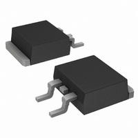
MBRB2060CT, MBR2060CT SWITCHMODEt Power Rectifiers 2 TO−220/D PAK Surface Mount Power Package These state−of−the−art devices employ the use of the Schottky Barrier principle with a platinum barrier metal. Features • Package Designed for Power Surface Mount Applications (D • 2 ...

Page 2

... J 3. Pulse Test: Pulse Width = 300 ms, Duty Cycle ≤ 2.0%. ORDERING INFORMATION Device MBRB2060CT MBRB2060CTG MBRB2060CTT4 MBRB2060CTT4G MBR2060CT MBR2060CTG †For information on tape and reel specifications, including part orientation and tape sizes, please refer to our Tape and Reel Packaging Specifications Brochure, BRD8011/D. ...

Page 3

INSTANTANEOUS VOLTAGE (VOLTS) F Figure 1. Typical Forward Voltage Per Diode 20 RATED VOLTAGE APPLIED R = 2°C/W qJC dc 15 SQUARE ...

Page 4

... SEATING PLANE 0.13 (0.005 VARIABLE CONFIGURATION ZONE VIEW W−W VIEW W−W 1 10.66 0.42 *For additional information on our Pb−Free strategy and soldering details, please download the ON Semiconductor Soldering and Mounting Techniques Reference Manual, SOLDERRM/D. PACKAGE DIMENSIONS 2 D PAK 3 CASE 418B−04 ISSUE VIEW W− ...

Page 5

... Opportunity/Affirmative Action Employer. This literature is subject to all applicable copyright laws and is not for resale in any manner. PUBLICATION ORDERING INFORMATION LITERATURE FULFILLMENT: Literature Distribution Center for ON Semiconductor P.O. Box 5163, Denver, Colorado 80217 USA Phone: 303−675−2175 or 800−344−3860 Toll Free USA/Canada Fax: 303− ...

Related keywords