MURF1660CT ON Semiconductor, MURF1660CT Datasheet

DIODE ULTRA FST 600V 8A TO220FP

MURF1660CT

Manufacturer Part Number
MURF1660CT
Description
DIODE ULTRA FST 600V 8A TO220FP
Manufacturer
ON Semiconductor
Series
SWITCHMODE™r
Datasheet

Specifications of MURF1660CT

Voltage - Forward (vf) (max) @ If
1.5V @ 8A
Current - Reverse Leakage @ Vr
10µA @ 600V
Current - Average Rectified (io) (per Diode)
8A
Voltage - Dc Reverse (vr) (max)
600V
Reverse Recovery Time (trr)
60ns
Diode Type
Standard
Speed
Fast Recovery =< 500ns, > 200mA (Io)
Diode Configuration
1 Pair Common Cathode
Mounting Type
Through Hole
Package / Case
TO-220-3 Full Pack (Straight Leads)
Product
Ultra Fast Recovery Rectifier
Configuration
Dual Common Cathode
Reverse Voltage
600 V
Forward Voltage Drop
1.5 V at 8 A
Recovery Time
60 ns
Forward Continuous Current
16 A
Max Surge Current
100 A
Reverse Current Ir
10 uA
Mounting Style
Through Hole
Maximum Operating Temperature
+ 150 C
Minimum Operating Temperature
- 65 C
Lead Free Status / RoHS Status
Contains lead / RoHS non-compliant
Other names
MURF1660CTOS

Available stocks

Company
Part Number
Manufacturer
Quantity
Price
Part Number:
MURF1660CT
Manufacturer:
TSC
Quantity:
10 000
Part Number:
MURF1660CT
Manufacturer:
INFCHN
Quantity:
17 940
Part Number:
MURF1660CTG
Manufacturer:
ON Semiconductor
Quantity:
319
Part Number:
MURF1660CTG
Manufacturer:
ON Semiconductor
Quantity:
800
Part Number:
MURF1660CTG
Manufacturer:
ON/安森美
Quantity:
20 000
MURF1660CT
SWITCHMODEt
Power Rectifier
power supplies, inverters and as free wheeling diodes.
Features
Mechanical Characteristics:
Stresses exceeding Maximum Ratings may damage the device. Maximum
Ratings are stress ratings only. Functional operation above the Recommended
Operating Conditions is not implied. Extended exposure to stresses above the
Recommended Operating Conditions may affect device reliability.
1. Proper strike and creepage distance must be provided.
*For additional information on our Pb-Free strategy and soldering details, please
MAXIMUM RATINGS
© Semiconductor Components Industries, LLC, 2007
June, 2007 - Rev. 5
download the ON Semiconductor Soldering and Mounting Techniques
Reference Manual, SOLDERRM/D.
Peak Repetitive Reverse Voltage
Working Peak Reverse Voltage
DC Blocking Voltage
Average Rectified Forward Current
Total Device, (Rated V
Peak Repetitive Forward Current
(Rated V
T
Non-repetitive Peak Surge Current
(Surge applied at rated load conditions
halfwave, single phase, 60 Hz)
Operating Junction and Storage Temperature
RMS Isolation Voltage
(t = 0.3 second, R.H. ≤ 30%, T
(Note 1) Per Figure 3
These state-of-the-art devices are designed for use in switching
Leads are Readily Solderable
C
Ultrafast 60 Nanosecond Recovery Times
150°C Operating Junction Temperature
Epoxy Meets UL 94 V-0 @ 0.125 in
High Temperature Glass Passivated Junction
Low Leakage Specified @ 150°C Case Temperature
Current Derating @ Both Case and Ambient Temperatures
Electrically Isolated. No Isolation Hardware Required.
Pb-Free Package is Available*
Case: Epoxy, Molded
Weight: 1.9 Grams (Approximately)
Finish: All External Surfaces Corrosion Resistant and Terminal
Lead Temperature for Soldering Purposes: 260°C Max. for 10 Seconds
Per Diode
Per Device
= 150°C
R
, Square Wave, 20 kHz),
Rating
R
), T
(Per Leg)
C
= 150°C
Preferred Device
A
= 25°C)
Symbol
T
V
V
I
V
I
J
F(AV)
I
RWM
FSM
RRM
V
, T
FM
iso1
R
stg
- 65 to +150
Value
4500
600
100
16
16
8
1
Unit
°C
V
A
A
A
V
Preferred devices are recommended choices for future use
and best overall value.
MURF1660CT
MURF1660CTG
1
2
3
Device
16 AMPERES, 600 VOLTS
ULTRAFAST RECTIFIER
ORDERING INFORMATION
A
Y
WW
U1660 = Device Code
G
AKA
2
ISOLATED TO-220
http://onsemi.com
CASE 221D
STYLE 3
= Assembly Location
= Year
= Work Week
= Pb-Free Package
= Diode Polarity
(Pb-Free)
Package
TO-220
TO-220
Publication Order Number:
MURF1660CT/D
50 Units/Rail
50 Units/Rail
1
3
MARKING
DIAGRAM
Shipping
U1660G
AYWW
A K A

Related parts for MURF1660CT

MURF1660CT Summary of contents

Page 1

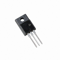
... ULTRAFAST RECTIFIER 16 AMPERES, 600 VOLTS MARKING DIAGRAM AYWW U1660G ISOLATED TO-220 CASE 221D STYLE Assembly Location Y = Year WW = Work Week U1660 = Device Code G = Pb-Free Package AKA = Diode Polarity ORDERING INFORMATION Device Package Shipping TO-220 50 Units/Rail TO-220 50 Units/Rail (Pb-Free) Publication Order Number: MURF1660CT/D ...

Page 2

... Pulse Test: Pulse Width = 300 ms, Duty Cycle ≤ 2.0%. 100 0.5 0.2 0.1 0 1.0 K 100 10 1.0 0.1 0.01 100 MURF1660CT (Per Leg 150°C J 100°C 0.6 0.8 1.0 1.2 1 INSTANTANEOUS VOLTAGE (V) F Figure 1. Typical Forward Voltage, Per Leg T = 150°C J 100°C 25°C ...

Page 3

... MURF1660CT TEST CONDITION FOR ISOLATION TEST* FULLY ISOLATED PACKAGE Figure 3. Mounting Position * Measurement made between leads and heatsink with all leads shorted together. MOUNTING INFORMATION CLIP HEATSINK Clip-Mounted Figure 4. Typical Mounting Technique http://onsemi.com 3 LEADS HEATSINK 0.110, MIN ...

Page 4

... BSC 5.08 BSC Q 0.122 0.138 3.10 3.50 R 0.099 0.117 2.51 2.96 S 0.092 0.113 2.34 2.87 U 0.239 0.271 6.06 6.88 STYLE 3: PIN 1. ANODE 2. CATHODE 3. ANODE ON Semiconductor Website: www.onsemi.com Order Literature: http://www.onsemi.com/orderlit For additional information, please contact your local Sales Representative MURF1660CT/D ...

Related keywords