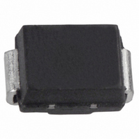
S1AB-13-F Diodes Inc, S1AB-13-F Datasheet - Page 2

S1AB-13-F
Manufacturer Part Number
S1AB-13-F
Description
DIODE GPP 1A 50V SMB
Manufacturer
Diodes Inc
Datasheet
1.S1B-13-F.pdf
(4 pages)
Specifications of S1AB-13-F
Voltage - Forward (vf) (max) @ If
1.1V @ 1A
Voltage - Dc Reverse (vr) (max)
50V
Current - Average Rectified (io)
1A
Current - Reverse Leakage @ Vr
5µA @ 50V
Diode Type
Standard
Speed
Standard Recovery >500ns, > 200mA (Io)
Reverse Recovery Time (trr)
3µs
Capacitance @ Vr, F
10pF @ 4V, 1MHz
Mounting Type
Surface Mount
Package / Case
DO-214AA, SMB
Product
Standard Recovery Rectifier
Configuration
Single
Reverse Voltage
50 V
Forward Voltage Drop
1.1 V
Recovery Time
3000 ns
Forward Continuous Current
1 A
Max Surge Current
30 A
Reverse Current Ir
5 uA
Mounting Style
SMD/SMT
Maximum Operating Temperature
+ 150 C
Minimum Operating Temperature
- 65 C
Lead Free Status / RoHS Status
Lead free by exemption / RoHS Compliant
Other names
Q2200396
S1AB-13-F
S1AB-FDITR
S1AB-13-F
S1AB-FDITR
Available stocks
Company
Part Number
Manufacturer
Quantity
Price
Company:
Part Number:
S1AB-13-F
Manufacturer:
DIODES
Quantity:
6 000
Part Number:
S1AB-13-F
Manufacturer:
DIODES/美台
Quantity:
20 000
Single phase, half wave, 60Hz, resistive or inductive load.
For capacitance load, derate current by 20%.
Thermal Characteristics
Electrical Characteristics
Maximum Ratings
Peak Repetitive Reverse Voltage
Working Peak Reverse Voltage
DC Blocking Voltage
RMS Reverse Voltage
Average Rectified Output Current
Non-Repetitive Peak Forward Surge Current
Typical Thermal Resistance, Junction to Terminal (Note 4)
Operating and Storage Temperature Range
Forward Voltage
Peak Reverse Leakage Current
at Rated DC Blocking Voltage
Reverse Recovery Time (Note 5)
Typical Total Capacitance
8.3ms Single half sine-wave superimposed on rated load
Notes:
S1A/B - S1M/B
Document number: DS16003 Rev. 20 - 2
1.0
0.8
0.6
0.4
0.2
4. Thermal resistance junction to terminal, unit mounted on PC board with 5.0 mm
5. Measured with I
6. Measured at 1.0MHz and applied reverse voltage of 4.0V DC.
0
40
Resistive or
inductive load
Fig. 1 Forward Current Derating Curve
60
T , TERMINAL TEMPERATURE ( C)
T
Characteristic
Characteristic
Characteristic
F
80
= 0.5A, I
@T
(Note 6)
A
100
= 25°C unless otherwise specified
R
= 1.0A, I
120
@T
RR
A
= 0.25A.
= 25°C unless otherwise specified
140
@ T
@ T
@ T
@ I
°
F
T
A
A
160
= 1.0A
= 100°C
= 25°C
= 125°C
180
www.diodes.com
Symbol
V
Symbol
V
V
R(RMS)
I
2 of 4
FSM
RWM
V
RRM
I
V
I
O
C
RM
t
R
FM
rr
T
Symbol
T
J,
R
T
θ JT
A/AB
STG
S1
50
35
2
0.01
1.0
0.1
(0.013 mm thick) copper pads as heat sink.
10
0
Min
V , INSTANTANEOUS FORWARD VOLTAGE (V)
B/BB
-
-
-
-
-
F
100
S1
70
Fig. 2 Typical Forward Characteristics
0.4
D/DB
200
140
S1
-65 to +150
Value
Typ
1.8
10
G/GB
30
-
-
-
400
280
1.0
S1
30
0.8
J/JB
600
420
S1
1.2
S1A/B - S1M/B
Max
100
1.1
5.0
3.0
K/KB
-
800
560
S1
© Diodes Incorporated
September 2010
°C/W
1.6
Unit
M/MB
1000
°C
700
S1
Unit
μA
pF
μs
V
Unit
V
V
A
A


