SBR2A30P1-7 Diodes Inc, SBR2A30P1-7 Datasheet
SBR2A30P1-7
Specifications of SBR2A30P1-7
SBR2A30P1-7DITR
Available stocks


Related parts for SBR2A30P1-7


SBR2A30P1-7 Summary of contents
Page 1
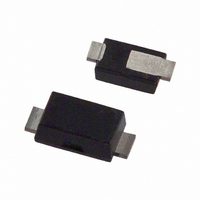
... Weight: 0.018 grams (approximate) Top View Symbol Value V RRM 30 V RWM R(RMS) 2 FSM Symbol Value R θ 175 R θ JA 100 R θ -65 to +150 J STG www.diodes.com SBR2A30P1 ® 2.0A SBR ® PowerDI 123 Unit Unit ºC/W ºC October 2008 © Diodes Incorporated ...
Page 2
... A Symbol Min Typ (BR)R - 0.23 - 0.34 0. 0.50 - 0.13 - 0.275 10,000 1,000 100 10,000 1,000 100 www.diodes.com SBR2A30P1 Max Unit Test Condition - 250µ 0.1A 1.0A 2.0A 4.0A 0. 0.1A 0. 1.0A 5V 25ºC 100 µ 200 µA ...
Page 3
... T , AMBIENT TEMPERATURE (°C) A Fig. 5 Forward Current Derating Curve Ordering Information (Note 6) Part Number SBR2A30P1-7 Notes: 6. For packaging details our website at http://www.diodes.com/datasheets/ap02007.pdf. Marking Information Date Code Key Year 2006 2007 Code T U Month Jan Feb Mar Code ...
Page 4
... All Dimensions Dimensions Y1 IMPORTANT NOTICE LIFE SUPPORT www.diodes.com SBR2A30P1 ® PowerDI 123 3.50 3.90 3.70 2.60 3.00 2.80 1.63 1.93 1.78 0.93 1.00 0.98 0.85 1.25 1.00 0.15 0.25 0.20 0.55 0.75 0.65 1.80 2.20 2.00 0.95 1.25 1.10 Value (in mm ...