D2T-T1 Omron, D2T-T1 Datasheet - Page 2
D2T-T1
Manufacturer Part Number
D2T-T1
Description
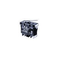
DOOR SWITCH
Manufacturer
Omron
Series
D2Tr
Type
Snap Actionr
Datasheet
1.D2T-T1.pdf
(4 pages)
Specifications of D2T-T1
Circuit
DPST-NO
Switch Function
Off-Mom
Contact Rating @ Voltage
5A @ 125VAC
Actuator Type
Round (Pin Plunger)
Mounting Type
Chassis Mount
Termination Style
Quick Connect - .110" (2.8mm)
Operating Force
330gf
Contact Form
DPST
Contact Rating
5 Amps at 125 Volts to 250 Volts, 0.1 Amp at 125 Volts
Actuator
Plunger, Pin
Lead Free Status / RoHS Status
Lead free / RoHS Compliant
Lead Free Status / RoHS Status
Lead free / RoHS Compliant
Other names
D2TT1


■ Ratings
Note: The ratings apply under the following test conditions: Ambient Temperature = 20±2°C, Ambient Humidity = 65±5%, Operating frequency = 30 operations/min.
■ Approved Standards
UL Recognized
CSA Certified
EN61058-1 (VDE approval)
Testing conditions: 5E4 (50,000 operations), T85 (0°C to 85°C)
Engineering Data
■ Contact Form
Note: The circuit switching power load has a snap-action mechanism.
38
Voltage
250 VAC
125 VAC
30 VDC
125 VAC
250 VAC
125 VAC
250 VAC
voltage
voltage
Rated
Rated
The circuit switching low-level load has a slow-action mecha-
nism.
Door Interlock Switch
Between terminals
Between terminals
DPST-NO
COM
Terminal 1
(Reference values)
1 and 2
1 and 2
- - -
5A
5A
5A
COM
Terminal 3
Power load
Micro load
NO
Terminal 4
(for 100,000 operations)
Between terminals 1 and 2
NO
Terminal 2
D2T
Between terminals
Between terminals
3 and 4
3 and 4
0.1A
0.1A
- - -
- - -
5A
5A
6A
■ Contact Specifications
Note: Minimum applicable loads are indicated by N standard refer-
■ Mounting Holes
All switches may be panel mounted using M3 mounting screws with
plane washers or spring washers to securely mount the switch.
Tighten the screws to a torque of 0.4 to 0.6 N·m
When mounting on a metal surface, be sure to provide a separator
between the switch and mounting plate.
Specification
Material
Gap (standard value)
Inrush current
Minimum applicable load
(see note)
Resistive Load
Panel Mount Holes
ence values. This value represents the failure rate at a 60%
(λ
The equation
rate of 1/2,000,000 operations can be expected at a reliability
level of 60%
Two, M3 screw holes
60
26.4±0.1
) reliability level (JIS C5003).
Item
λ
60
=0.5 x 10
Between terminals 3 and 4
Rivet
Silver
1 mm
60 A max.
160 mA at 5 VDC 1 mA at 5 VDC
11.9
-6
Panel Cutout Dimensions
Terminals
(Panel thickness: 1.5 to 2 mm)
1 and 2
/ operations indicates that a failure
+0.2
–0
0.1A
0.1A
- - -
Four, 0.5R max.
31.0
Plated
1.4 mm
- - -
+0.2
–0
Terminals
3 and 4
Related parts for D2T-T1
Image
Part Number
Description
Manufacturer
Datasheet
Request
R

Part Number:
Description:
Basic Switch
Manufacturer:
Omron
Datasheet:

Part Number:
Description:
Switch, SubMiniature, Snap Action, PIN PLUNGER, PCB Terminal, Standard LOAD Actuator
Manufacturer:
Omron
Datasheet:

Part Number:
Description:
G6S-2GLow Signal Relay
Manufacturer:
Omron Corporation
Datasheet:
Part Number:
Description:
Compact, Low-cost, SSR Switching 5 to 20 A
Manufacturer:
Omron Corporation
Datasheet:
Part Number:
Description:
Manufacturer:
Omron Corporation
Datasheet:
Part Number:
Description:
Manufacturer:
Omron Corporation
Datasheet:
Part Number:
Description:
Manufacturer:
Omron Corporation
Datasheet:
Part Number:
Description:
Manufacturer:
Omron Corporation
Datasheet: