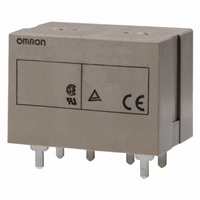
G7L-2A-P-CB-DC24 Omron, G7L-2A-P-CB-DC24 Datasheet - Page 2

G7L-2A-P-CB-DC24
Manufacturer Part Number
G7L-2A-P-CB-DC24
Description
RELAY
Manufacturer
Omron
Series
G7Lr
Specifications of G7L-2A-P-CB-DC24
Relay Type
General Purpose
Coil Resistance
303 Ohms
Coil Type
Standard
Contact Form
DPST (2 Form A)
Contact Rating (current)
20A
Switching Voltage
250VAC - Max
Coil Current
79mA
Coil Voltage
24VDC
Turn On Voltage (max)
18 VDC
Turn Off Voltage (min)
3.6 VDC
Mounting Type
Through Hole
Termination Style
PC Pin
Circuit
DPST (2 Form A)
Contact Rating @ Voltage
20A @ 220VAC
Control On Voltage (max)
18 VDC
Control Off Voltage (min)
3.6 VDC
Contact Rating
10 A at 120 VAC
Contact Termination
Solder Terminal
Mounting Style
Bracket
Power Consumption
1.9 W
Contact Material
Silver
Coil Voltage Vdc Nom
24V
Contact Current Max
20A
Contact Voltage Ac Nom
220V
Contact Configuration
DPST-NO
Lead Free Status / RoHS Status
Lead free / RoHS Compliant
Lead Free Status / RoHS Status
Lead free / RoHS Compliant
Other names
G7L-2A-P-CB-DC24
G7L-2A-PCB-DC24
G7L2APCBDC24
Z2582
G7L-2A-PCB-DC24
G7L2APCBDC24
Z2582
■ Model Number Legend
■ Accessories
Quick-connect Terminals
Note: A socket terminal cover is supplied with the P7LF-06 socket and does not attach directly to the G7L relays. It cannot be purchased separately.
Screw Terminals
Note: The P7LF-C terminal cover attaches directly to the G7L-B style relays. It is sold separately.
Specifications
■ Contact Data
Note: P level: λ
■ Coil Internal Circuit
DC operating coil
306
G7L- ❏ ❏ - ❏ ❏ ❏ ❏
1. Contact form
2. Terminal shape
E-brackets
Track mounting adaptor
Front connecting socket
E-brackets
Track mounting adaptor
Terminal Cover
Rated load
Contact material
Carry current
Max. operating voltage
Max. operating current
Max. switching capacity 6,600 VA
Min. permissible load
1A:SPST-NO
2A:DPST-NO
T:Quick-connect terminals
P:PCB terminals
B:Screw terminals
1 2
Description
Description
Load
3 4 5 6
General Purpose Relay
60
= 0.1 x 10
-6
G7L-1A-T
G7L-1A-B
30 A, 220 VAC
AgSnIn
30 A
250 VAC
30 A
100 mA, 5 VDC (please inquire for lower minimum rating)
Resistive load
operation.
(cosφ = 1)
G7L-1A-T, G7L-1A-B
SPST-NO
SPST-NO
G7L
25 A, 220 VAC
5,500 VA
Inductive load
(cosφ = 0.4)
G7L-1A-TJ
G7L-1A-BJ
3. Mounting construction
4. Special functions
No symbol:E bracket type
UB:Upper bracket type
No symbol:Without test button
J:With test button
AC operating coil
Contact form
Contact form
25 A
25 A
Resistive load
Model
Model
(cosφ = 1)
G7L-2A-T
G7L-2A-B
G7L-2A-T, G7L-2A-B
Inductive load
(cosφ = 0.4)
DPST-NO
DPST-NO
G7L-2A-TJ
G7L-2A-BJ
5. 80: VDE approved version
6. CB: Class B insulation
7. Rated coil voltage
20 A, 220 VAC
20 A
20 A
4,400 VA
(includes UL, CSA and TÜV)
Resistive load
(cosφ = 1)
G7L-1A-P, G7L-2A-P
R99-07G5D
P7LF-D
P7LF-06
R99-07G5D
P7LF-D
P7LF-C
Inductive load
(cosφ = 0.4)
Model
Model


