SBR10U45SP5-13 Diodes Inc, SBR10U45SP5-13 Datasheet - Page 2
SBR10U45SP5-13
Manufacturer Part Number
SBR10U45SP5-13
Description
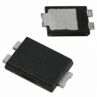
DIODE SBR 10A 45V POWERDI5
Manufacturer
Diodes Inc
Series
SBR®r
Datasheet
1.SBR10U45SP5-13.pdf
(5 pages)
Specifications of SBR10U45SP5-13
Voltage - Forward (vf) (max) @ If
470mV @ 10A
Voltage - Dc Reverse (vr) (max)
45V
Current - Average Rectified (io)
10A
Current - Reverse Leakage @ Vr
300µA @ 45V
Diode Type
Super Barrier
Speed
Fast Recovery =< 500ns, > 200mA (Io)
Mounting Type
Surface Mount
Package / Case
PowerDI™ 5
Lead Free Status / RoHS Status
Lead free / RoHS Compliant
Reverse Recovery Time (trr)
-
Capacitance @ Vr, F
-
Other names
SBR10U45SP5-13
SBR10U45SP5-13DITR
SBR10U45SP5-13DITR
Available stocks
Company
Part Number
Manufacturer
Quantity
Price
Company:

Part Number:
SBR10U45SP5-13
Manufacturer:
Diodes Inc
Quantity:
26 808
Part Number:
SBR10U45SP5-13
Manufacturer:
DIODES/美台
Quantity:
20 000


Single phase, half wave, 60Hz, resistive or inductive load.
For capacitance load, derate current by 20%.
Thermal Characteristics
Electrical Characteristics
Maximum Ratings
SBR and PowerDI are registered trademarks of Diodes Incorporated.
Peak Repetitive Reverse Voltage
Working Peak Reverse Voltage
DC Blocking Voltage
RMS Reverse Voltage
Average Rectified Output Current
Non-Repetitive Peak Forward Surge Current 8.3ms
Single Half Sine-Wave Superimposed on Rated Load
Repetitive Peak Avalanche Power (1μs, 25°C)
Maximum Thermal Resistance
Thermal Resistance Junction to Ambient (Note 3)
Thermal Resistance Junction to Ambient (Note 4)
Operating Temperature Range
Storage Temperature Range
Reverse Breakdown Voltage (Note 5)
Forward Voltage Drop
Leakage Current (Note 5)
Notes:
SBR10U45SP5
Document number: DS31371 Rev. 6 - 2
3. FR-4 PCB, 2oz. Copper, minimum recommended pad layout per http://www.diodes.com.
4. Polymide PCB, 2oz. Copper. Cathode pad dimensions 18.8mm x 14.4mm. Anode pad dimensions 5.6mm x 14.4mm.
5. Short duration pulse test used to minimize self-heating effect.
Characteristic
Characteristic
Characteristic
@T
A
= 25°C unless otherwise specified
@T
A
Symbol
= 25°C unless otherwise specified
V
(BR)R
V
I
R
F
DC Forward Mode
V
V
R
R
≤ 80% V
≤ 50% V
Min
45
-
-
-
-
-
-
www.diodes.com
RRM
RRM
2 of 5
Symbol
Symbol
V
V
V
P
T
R(RMS)
I
R
R
V
FSM
RWM
RRM
ARM
T
STG
I
RM
θ JA
θ JA
O
J
0.42
0.38
0.05
28.0
Typ
-
-
-
Max
0.42
0.47
0.41
0.3
15
75
-
-65 to +150
-65 to +175
Value
30000
Value
≤180
≤200
275
45
32
10
73
31
Unit
mA
V
V
I
I
I
I
V
V
V
R
F
F
F
SBR10U45SP5
R
R
R
= 8A, T
= 10A, T
= 10A, T
= 0.3mA
= 45V, T
= 45V, T
= 45V, T
Test Condition
J
© Diodes Incorporated
J
J
= 25ºC
December 2010
J
J
J
= 25ºC
= 125ºC
= 25ºC
= 100ºC
= 150ºC
ºC/W
Unit
Unit
ºC
ºC
W
V
V
A
A
Related parts for SBR10U45SP5-13
Image
Part Number
Description
Manufacturer
Datasheet
Request
R

Part Number:
Description:
Diodes (General Purpose, Power, Switching) 240V 350mW
Manufacturer:
Diodes Inc
Datasheet:

Part Number:
Description:
Diodes (General Purpose, Power, Switching) -
Manufacturer:
Diodes Inc
Part Number:
Description:
Diodes (General Purpose, Power, Switching) -
Manufacturer:
Diodes Inc

Part Number:
Description:
Diodes (General Purpose, Power, Switching) NPN Small SIG 50V 45V VCEO 6.0V VEBO
Manufacturer:
Diodes Inc
Datasheet:
Part Number:
Description:
Diodes (General Purpose, Power, Switching) NPN Small SIG 30V 30V VCEO 5.0V VEBO
Manufacturer:
Diodes Inc
Datasheet:
Part Number:
Description:
Diodes (General Purpose, Power, Switching) NPN Small SIG -80V -65V VCEO -5.0 VEBO
Manufacturer:
Diodes Inc
Datasheet:
Part Number:
Description:
Diodes (General Purpose, Power, Switching) NPN Small SIG -50V -45V VCEO 6.0V VEBO
Manufacturer:
Diodes Inc
Part Number:
Description:
Diodes (General Purpose, Power, Switching) Dual Switching DIODE 100V Vrm 75Vrrm 53Vr
Manufacturer:
Diodes Inc
Datasheet:

Part Number:
Description:
Diodes (General Purpose, Power, Switching) Vr/80V Io/125mA T/R
Manufacturer:
Diodes Inc
Datasheet:

Part Number:
Description:
Diodes (General Purpose, Power, Switching) HV DUAL SW DIODE 300V
Manufacturer:
Diodes Inc
Datasheet:

Part Number:
Description:
Diodes (General Purpose, Power, Switching) 80V 150mW
Manufacturer:
Diodes Inc
Datasheet:
Part Number:
Description:
Diodes (General Purpose, Power, Switching) 75V 150mW
Manufacturer:
Diodes Inc
Datasheet:

Part Number:
Description:
Diodes (General Purpose, Power, Switching) 200MW 80V
Manufacturer:
Diodes Inc
Part Number:
Description:
Diodes (General Purpose, Power, Switching) 100V Io/150mA T/R INVALID P/N
Manufacturer:
Diodes Inc

Part Number:
Description:
Diodes (General Purpose, Power, Switching) 350MW 75V
Manufacturer:
Diodes Inc