15ETL06FPPBF Vishay, 15ETL06FPPBF Datasheet - Page 4
15ETL06FPPBF
Manufacturer Part Number
15ETL06FPPBF
Description
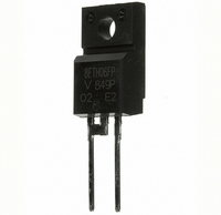
DIODE HYPERFAST 600V 15A TO220FP
Manufacturer
Vishay
Series
FRED Pt™r
Datasheet
1.15ETL06FPPBF.pdf
(9 pages)
Specifications of 15ETL06FPPBF
Voltage - Forward (vf) (max) @ If
1.05V @ 15A
Voltage - Dc Reverse (vr) (max)
600V
Current - Average Rectified (io)
15A
Current - Reverse Leakage @ Vr
10µA @ 600V
Diode Type
Standard
Speed
Fast Recovery =< 500ns, > 200mA (Io)
Reverse Recovery Time (trr)
270ns
Mounting Type
Through Hole
Package / Case
TO-220-2 Full Pack Fused Center, ITO-220AC
Product
Ultra Fast Recovery Rectifier
Configuration
Single
Reverse Voltage
600 V
Forward Voltage Drop
1.05 V
Recovery Time
270 ns
Forward Continuous Current
15 A
Max Surge Current
250 A
Reverse Current Ir
10 uA
Mounting Style
Through Hole
Maximum Operating Temperature
+ 175 C
Minimum Operating Temperature
- 65 C
Lead Free Status / RoHS Status
Lead free / RoHS Compliant
Capacitance @ Vr, F
-
Lead Free Status / RoHS Status
Lead free / RoHS Compliant, Lead free / RoHS Compliant
Other names
*15ETL06FPPBF
VS-15ETL06FPPBF
VS-15ETL06FPPBF
VS15ETL06FPPBF
VS15ETL06FPPBF
VS-15ETL06FPPBF
VS-15ETL06FPPBF
VS15ETL06FPPBF
VS15ETL06FPPBF


Document Number: 94004
15ETL06PbF, 15ETL06FPPbF
Bulletin
180
170
160
150
140
130
25
20
15
10
Fig. 8 - Forward Power Loss Characteristics
Fig. 6 - Max. Allowable Case Temperature
5
0
PD-20890 rev. A 10/06
0
0
Square wave (D = 0.50)
Rated Vr applied
see note (3)
Average Forward Current - I
Average Forward Current - I
Vs. Average Forward Current
0.01
5
5
0.1
0.00001
10
1
Fig. 5 - Max. Thermal Impedance Z
DC
10
D = 0.50
D = 0.20
D = 0.10
D = 0.05
D = 0.02
D = 0.01
10
0.0001
RMS Limit
15
15
DC
(Thermal Resistance)
t
Single Pulse
1
D = 0.01
D = 0.02
D = 0.05
D = 0.1
D = 0.2
D = 0.5
F
, Rectangular Pulse Duration (Seconds)
F
20
20
(AV)
(AV)
0.001
(A)
(A)
25
25
0.01
thJC
Characteristics (FULLPACK)
0.1
Notes:
1. Duty factor D = t1/ t2
2. Peak Tj = Pdm x ZthJC + Tc
(3) Formula used: T
180
160
140
120
100
80
Vs. Average Forward Current (FULLPACK)
Pd = Forward Power Loss =
(see Fig. 8);
Pd
I
Fig. 7 - Max. Allowable Case Temperature
I
R
F(AV)
0
@ V
REV
1
Square wave (D = 0.50)
80% Rated Vr applied
see note (3)
Average Forward Current - I
x V
R1
= Inverse Power Loss = V
FM
= rated V
P
5
@ (I
DM
F(AV)
10
1 t
C
2 t
R
= T
10
/
J
D)
- (Pd + Pd
100
www.vishay.com
15
DC
REV
R1
x I
) x R
R
20
(1 - D);
F
(AV)
thJC
(A)
;
25
4
Related parts for 15ETL06FPPBF
Image
Part Number
Description
Manufacturer
Datasheet
Request
R

Part Number:
Description:
DIODE HYPERFAST 600V 15A TO220AC
Manufacturer:
Vishay
Datasheet:

Part Number:
Description:
DIODE HYPERFAST 600V 15A TO262
Manufacturer:
Vishay
Datasheet:

Part Number:
Description:
DIODE HYPERFAST 600V 15A TO-262
Manufacturer:
Vishay
Datasheet:

Part Number:
Description:
Ultralow VF Hyperfast Rectifier for Discontinuous Mode PFC, 15 A FRED PtTM
Manufacturer:
VISHAY [Vishay Siliconix]
Datasheet:
Part Number:
Description:
Ultralow VF Hyperfast Rectifier for Discontinuous Mode PFC, 15 A FRED Pt
Manufacturer:
VISHAY [Vishay Siliconix]
Datasheet:
Part Number:
Description:
Ultralow VF Hyperfast Rectifier for Discontinuous Mode PFC, 15 A FRED Pt�
Manufacturer:
VISHAY [Vishay Siliconix]
Datasheet:

Part Number:
Description:
357-036-542-201 CARDEDGE 36POS DL .156 BLK LOPRO
Manufacturer:
Vishay
Datasheet:
Part Number:
Description:
357-036-542-201 CARDEDGE 36POS DL .156 BLK LOPRO
Manufacturer:
Vishay
Datasheet:
Part Number:
Description:
357-036-542-201 CARDEDGE 36POS DL .156 BLK LOPRO
Manufacturer:
Vishay
Datasheet:
Part Number:
Description:
357-036-542-201 CARDEDGE 36POS DL .156 BLK LOPRO
Manufacturer:
Vishay
Datasheet:
Part Number:
Description:
357-036-542-201 CARDEDGE 36POS DL .156 BLK LOPRO
Manufacturer:
Vishay
Datasheet:
Part Number:
Description:
357-036-542-201 CARDEDGE 36POS DL .156 BLK LOPRO
Manufacturer:
Vishay
Datasheet:
Part Number:
Description:
357-036-542-201 CARDEDGE 36POS DL .156 BLK LOPRO
Manufacturer:
Vishay
Datasheet:
Part Number:
Description:
357-036-542-201 CARDEDGE 36POS DL .156 BLK LOPRO
Manufacturer:
Vishay
Datasheet:
Part Number:
Description:
357-036-542-201 CARDEDGE 36POS DL .156 BLK LOPRO
Manufacturer:
Vishay
Datasheet: