HFA30PB120PBF Vishay, HFA30PB120PBF Datasheet - Page 5
HFA30PB120PBF
Manufacturer Part Number
HFA30PB120PBF
Description
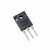
DIODE HEXFRED 1200V 30A TO247AC
Manufacturer
Vishay
Series
HEXFRED®r
Specifications of HFA30PB120PBF
Diode Type
Standard
Voltage - Forward (vf) (max) @ If
4.1V @ 30A
Voltage - Dc Reverse (vr) (max)
1200V (1.2kV)
Current - Average Rectified (io)
30A
Current - Reverse Leakage @ Vr
40µA @ 1200V
Speed
Fast Recovery =< 500ns, > 200mA (Io)
Reverse Recovery Time (trr)
170ns
Mounting Type
Through Hole, Radial
Package / Case
TO-247-2 (TO-247AC Modified)
Product
Ultra Fast Recovery Rectifier
Configuration
Single
Reverse Voltage
1200 V
Forward Voltage Drop
5.7 V at 60 A
Recovery Time
170 ns
Forward Continuous Current
30 A
Max Surge Current
120 A
Reverse Current Ir
40 uA
Mounting Style
Through Hole
Maximum Operating Temperature
+ 150 C
Minimum Operating Temperature
- 55 C
Repetitive Reverse Voltage Vrrm Max
1.2kV
Forward Current If(av)
30A
Forward Voltage Vf Max
5.7V
Reverse Recovery Time Trr Max
170ns
Forward Surge Current Ifsm Max
120A
Rectifier Type
Switching Diode
Peak Rep Rev Volt
1200V
Avg. Forward Curr (max)
30A
Rev Curr
40uA
Peak Non-repetitive Surge Current (max)
120A
Forward Voltage
5.7V
Operating Temp Range
-55C to 150C
Package Type
TO-247AC
Rev Recov Time
170ns
Operating Temperature Classification
Military
Mounting
Through Hole
Pin Count
3 +Tab
Lead Free Status / RoHS Status
Lead free / RoHS Compliant
Capacitance @ Vr, F
-
Lead Free Status / Rohs Status
Lead free / RoHS Compliant
Other names
*HFA30PB120PBF
VS-HFA30PB120PBF
VS-HFA30PB120PBF
VSHFA30PB120PBF
VSHFA30PB120PBF
VS-HFA30PB120PBF
VS-HFA30PB120PBF
VSHFA30PB120PBF
VSHFA30PB120PBF
Available stocks
Company
Part Number
Manufacturer
Quantity
Price
Company:

Part Number:
HFA30PB120PBF
Manufacturer:
Vishay Semiconductors
Quantity:
54


Document Number: 94069
Revision: 16-Sep-08
Current
monitor
D.U.T.
(1) dI
(2) I
(3) t
0
L = 100 µH
from zero crossing point of negative
going I
through 0.75 I
extrapolated to zero current.
through zero crossing
RRM
rr
R
I
F
F
- reverse recovery time measured
g
/dt - rate of change of current
= 25 Ω
- peak reverse recovery current
F
For technical questions, contact: diodes-tech@vishay.com
to point where a line passing
Fig. 10 - Reverse Recovery Waveform and Definitions
Fig. 9 - Reverse Recovery Parameter Test Circuit
Fig. 11 - Avalanche Test Circuit and Waveforms
RRM
and 0.50 I
HEXFRED® Ultrafast Soft
(1)
Freewheel
adjust
dI
F
diode
/dt
dI
High-speed
F
/dt
RRM
switch
L = 70 µH
G
V
d
t
a
= 50 V
(2)
V
(3)
+
R
= 200 V
I
RRM
t
0.01 Ω
D
rr
S
(4) Q
(5) dI
IRFP250
and I
current during t
rr
(rec)M
0.75 I
- area under curve defined by t
RRM
t
D.U.T.
b
/dt - peak rate of change of
RRM
dI
0.5 I
Q
(rec)M
rr
Q
=
RRM
b
Vishay High Power Products
rr
/dt
portion of t
t
(4)
rr
V
x I
(5)
2
R(RATED)
RRM
I
V
L(PK)
(AVAL)
rr
HFA30PB120PbF
rr
Decay
time
www.vishay.com
5
Related parts for HFA30PB120PBF
Image
Part Number
Description
Manufacturer
Datasheet
Request
R

Part Number:
Description:
357-036-542-201 CARDEDGE 36POS DL .156 BLK LOPRO
Manufacturer:
Vishay
Datasheet:
Part Number:
Description:
357-036-542-201 CARDEDGE 36POS DL .156 BLK LOPRO
Manufacturer:
Vishay
Datasheet:
Part Number:
Description:
357-036-542-201 CARDEDGE 36POS DL .156 BLK LOPRO
Manufacturer:
Vishay
Datasheet:
Part Number:
Description:
357-036-542-201 CARDEDGE 36POS DL .156 BLK LOPRO
Manufacturer:
Vishay
Datasheet:
Part Number:
Description:
357-036-542-201 CARDEDGE 36POS DL .156 BLK LOPRO
Manufacturer:
Vishay
Datasheet:
Part Number:
Description:
357-036-542-201 CARDEDGE 36POS DL .156 BLK LOPRO
Manufacturer:
Vishay
Datasheet:
Part Number:
Description:
357-036-542-201 CARDEDGE 36POS DL .156 BLK LOPRO
Manufacturer:
Vishay
Datasheet:
Part Number:
Description:
357-036-542-201 CARDEDGE 36POS DL .156 BLK LOPRO
Manufacturer:
Vishay
Datasheet:
Part Number:
Description:
357-036-542-201 CARDEDGE 36POS DL .156 BLK LOPRO
Manufacturer:
Vishay
Datasheet:
Part Number:
Description:
357-036-542-201 CARDEDGE 36POS DL .156 BLK LOPRO
Manufacturer:
Vishay
Datasheet:
Part Number:
Description:
357-036-542-201 CARDEDGE 36POS DL .156 BLK LOPRO
Manufacturer:
Vishay
Datasheet:
Part Number:
Description:
357-036-542-201 CARDEDGE 36POS DL .156 BLK LOPRO
Manufacturer:
Vishay
Datasheet:
Part Number:
Description:
357-036-542-201 CARDEDGE 36POS DL .156 BLK LOPRO
Manufacturer:
Vishay
Datasheet:
Part Number:
Description:
357-036-542-201 CARDEDGE 36POS DL .156 BLK LOPRO
Manufacturer:
Vishay
Datasheet:
Part Number:
Description:
357-036-542-201 CARDEDGE 36POS DL .156 BLK LOPRO
Manufacturer:
Vishay
Datasheet: