LY1-AC110/120 Omron, LY1-AC110/120 Datasheet
LY1-AC110/120
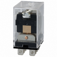
Specifications of LY1-AC110/120
LY1AC110/120
LY1AC110120
Z781
Available stocks


Related parts for LY1-AC110/120


LY1-AC110/120 Summary of contents
Page 1
... LED indicator, diode surge suppression, push-to-test button circuit. • All models meet UL and CSA approvals; VDE, LR, and SEV approved versions are available. Ordering Information To Order: Select the part number and add the desired coil voltage rating (e.g., LY1-DC6). Type Terminal Standard Plug-in/solder SPDT ...
Page 2
... SPDT PT08-0 DPDT 3PDT PT11-0 4PDT PT14-0 2 General Purpose Relay Contact form Single contact Standard Upper bracket mounting mounting bracket LY1l4 — — LY2l4 — — LY3l4 — — LY4l4 — — LY2l4N — — LY4l4N — — Relay hold-down clip ...
Page 3
Specifications ■ Contact Data Load SPDT Resistive load (p. Rated load 110 VAC 110 VAC VDC VDC Contact material Ag-Alloy Carry current 15 A ...
Page 4
Type – AC Rated Rated current (mA) voltage (V) resistance 310 270 6.70 12 159 134 100 410 100/110 15.90/18.30 13.60/15.60 2,300 120 17.30 14.8 2,450 200/220 ...
Page 5
... Weight Note: Data shown are of initial value. ■ Characteristic Data Maximum switching capacity LY1 LY2 Rated operating voltage (V) Rated operating voltage (V) Electrical service life LY1 LY2 Switching current (A) Switching current (A) 50 mΩ max max max. 18,000 operations/hour 1,800 operations/hour 100 MΩ min. (at 500 VDC) ...
Page 6
... LY1-0, LY2-0, LY3-0, LY4-0 Note: The above drawing shows LY2-0. With LY1-0, dimension “*” should read as eight 6.35 (.25). LY1F, LY2F Note: The above drawing shows LY1F. With LY2F, dimension “*” should read as eight 3.05 mm (0.12 in) dia. holes. 6 General Purpose Relay ...
Page 7
... LY4F LY1S, LY2S Note: The above drawing shows LY2S-US. With LY1S-US, dimension “*” should read as eight 2.03 mm (0.08 in) dia. holes. LY3S LY4S Mounting holes Round hole Rectangular hole Round hole Rectangular hole Round hole Rectangular hole General Purpose Relay LY 7 ...
Page 8
Accessories Unit: mm (inch) Track mounted sockets (UL File No. E87929) (CSA Report No. LR31928) PTF08A Terminal arrangement/ (see note 3) mounting holes (Top view) Track mounting sockets (UL File No. E87929) (CSA Report No. LR31928) PTF14A Terminal arrangement/ ...
Page 9
Back connecting socket (UL File No. E87929) (CSA Report No. LR31928) PT14 Terminal arrangement (Bottom view) Note: Values in brackets for LY❏CR. Back connecting socket (UL File No. E87929) (CSA Report No. LR31928) PT08QN Panel cut-out and terminal arrangement are ...
Page 10
Unit: mm (inch) Relay hold-down clips PYC-A1 For PTF❏A socket Relay hold-down clips PYC-P2 For push-to-test button type with PT❏ socket Mounting track/end plate/spacer PFP-100N/PFP-50N mounting track 10 General Purpose Relay PYC-S For relay mounting plates (Applicable to Type PYP-1 ...
Page 11
PFP-100N2 mounting track *This dimension is 14.99 mm (0.59 in) on both ends in the case of PFP-100N, but on one end in the case of PFP-50N. **L = Length PFP-50N L = 497.84 mm (19.60 in) PFP-100N L = ...
Page 12
Relay Options LED Indicator Specifications and dimensions same as the Standard Type with the following exception. With the LED indicator type, the rated current is approxi- mately 0 to 5.0 mA higher than the Standard Type. Terminal arrangement/Internal connections ...
Page 13
... Push-to-test Button Specifications and dimensions same as the Standard Type with the following exceptions. LY❏12 Note: Type LY112 has the same dimensions and appearances as Type LY212 shown except that dimensions “*” is 2.03 mm (0.08 in) dia. holes. LY312 With RC circuit Terminal arrangement/Internal connections (Bottom view) ...
Page 14
Approvals UL Recognized Type (File No. E41643) Type Contact form LY❏ SPDT LY❏ DPDT LY❏ 3PDT 4PDT CSA Certified Type (File No. LR31928) Type Contact form LY❏ SPDT LY❏ DPDT LY❏ 3PDT 4PDT VDE Approved Type (File No. 9903 ...
Page 15
... III. PRECAUTIONS 1. Suitability THE BUYER’S SOLE RESPOINSIBILITY TO ENSURE THAT ANY OMRON PRODUCT IS FIT AND SUFFICIENT FOR USE IN A MOTORIZED VEHICLE APPLICATION. BUYER SHALL BE SOLELY RESPONSIBLE FOR DETERMINING APPROPRIATENESS OF THE PARTICULAR PRODUCT WITH RESPECT TO THE BUYER’S APPLICATION INCLUDING (A) ELECTRICAL OR ELECTRONIC COMPONENTS, (B) CIRCUITS, (C) SYSTEM ASSEMBLIES, (D) END PRODUCT, (E) SYSTEM, (F) MATERIALS OR SUBSTANCES OR (G) OPERATING ENVIRONMENT ...
Page 16
... THE OMRON PRODUCT IS PROPERLY RATED AND INSTALLED FOR THE INTENDED USE WITHIN THE OVERALL EQUIPMENT OR SYSTEM. Complete “Terms and Conditions of Sale” for product purchase and use are on Omron’s website at http://www.components.omron.com – under the “About Us” tab, in the Legal Matters section. ...