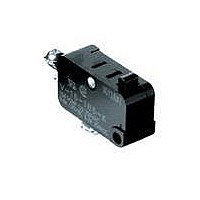
VAL2 Omron, VAL2 Datasheet

VAL2
Specifications of VAL2
Related parts for VAL2
VAL2 Summary of contents
Page 1
... Short hinge lever 2: Hinge lever 3: Long hinge lever 4: Simulated roller lever 5: Short hinge roller lever 6: Hinge roller lever Note: Consult Omron regarding nominclature combinations and part numbers not found in this datasheet. 4. Contact Form COM Terminal, Bottom position: 1: SPDT 2: SPST-NC 3: SPST-NO COM Terminal, Side position: ...
Page 2
... Note: 1. Add “G” to the part number in the appropriate location to obtain a 0.5 mm contact gap. Add “-K” to the part number in the appropriate location to obtain 2.9 mm mounting holes. Example: V-21G2-1C6-K 2. Not all combinations are available. Consult Omron regarding nomenclature combinations and part numbers not found in this datasheet. V ...
Page 3
... Note: 1. Add “G” to the part number in the appropriate location to obtain a 0.5 mm contact gap. Add “-K” to the part number in the appropriate location to obtain 2.9 mm mounting holes. Examples: 1) V-16G3-1C25-K 2) V-11G-1A4-K 2. Not all combinations are available. Consult Omron regarding nomenclature combinations and part numbers not found in this datasheet. Without barrier ...
Page 4
... Add “C2” to the part number in the appropriate location to obtain versions with #187 quick- connect terminals. Example: 1) V-15G1-1C25-T-K 2. Not all combinations are available. Consult Omron regarding nomenclature combinations and part numbers not found in this datasheet. V 124 ...
Page 5
Specifications ■ Ratings (reference values) Type Rated voltage Resistive load NC V-21 250 VAC 8 VDC 30 VDC 125 VDC 250 VDC V-16 250 VAC 8 VDC 30 VDC 125 VDC 250 VDC V-15 250 VAC 8 VDC 30 VDC ...
Page 6
... The dielectric strength shown is measured using a separator between the switch and metal mounting plate. 3. For pin plunger models, the above values apply for use at both the free position and total travel position. For lever models, they apply at the total travel position. 4. For testing conditions, contact your OMRON sales representative. ■ Contact Specifications Item ...
Page 7
... Bottom type Side type * The SPST-NC and SPST-NO contact form types listed in the ordering information tables are for Pin Plunger models only. For information concerning lever models consult Omron. ■ Electrical service life (Pin plunger models) V-21/-16/-15 5 Operating frequency: 60 operations/min cosφ ...
Page 8
Dimensions ■ Terminals Note: 1. Unless otherwise specified, all units are in millimeters and a tolerance of ±0.4 mm applies to all dimensions 2. The following table is for the SPDT contact specifications. Two terminals will be available for SPST-NO ...
Page 9
Dimensions and Operating Characteristics Thermoplastic Case Models Note: 1. Unless otherwise specified, all units are in millimeters and a tolerance of ±0.4 mm applies to all dimensions 2. The following illustrations and drawings are for quick-connect terminals (#250) (terminals ...
Page 10
Note: 1. Unless otherwise specified, all units are in millimeters and a tolerance of ±0.4 mm applies to all dimensions 2. The following illustrations and drawings are for quick-connect terminals (#250) (terminals C). V models also incorporate terminals A and ...
Page 11
Note: 1. Unless otherwise specified, all units are in millimeters and a tolerance of ±0.4 mm applies to all dimensions 2. The following illustrations and drawings are for quick-connect terminals (#250) (terminals C). V models also incorporate terminals A and ...
Page 12
Thermosetting Case Models Note: 1. Unless otherwise specified, all units are in millimeters and a tolerance of ±0.4 mm applies to all dimensions 2. The following illustrations are for quick-connect terminals (#250) (terminals C). Refer to Terminals section for the ...
Page 13
Note: 1. Unless otherwise specified, all units are in millimeters and a tolerance of ±0.4 mm applies to all dimensions 2. The following illustrations are for quick-connect terminals (#250) (terminals C). Refer to Terminals section for the dimensions of other ...
Page 14
... Precautions Be sure to read the precautions and information common to all Snap Action and Detection Switches, contained in the Technical User’s Guide, “Snap Action Switches, Technical Information” for correct use. ■ Correct Use Terminal Connection To solder the lead to the solder terminal, apply a soldering iron rated max ...
Page 15
MEMO V Snap Action Switch ...
Page 16
... All sales are subject to Omron Electronic Components LLC standard terms and conditions of sale, which can be found at http://www.components.omron.com/components/web/webfiles.nsf/sales_terms.html ALL DIMENSIONS SHOWN ARE IN MILLIMETERS. To convert millimeters into inches, multiply by 0.03937. To convert grams into ounces, multiply by 0.03527. OMRON ELECTRONIC COMPONENTS LLC 55 E. Commerce Drive, Suite B ...


