XF2J-1024-11A-R100 Omron, XF2J-1024-11A-R100 Datasheet - Page 26
XF2J-1024-11A-R100
Manufacturer Part Number
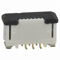
XF2J-1024-11A-R100
Description
FPC Connector (100-pc Reel)
Manufacturer
Omron
Series
XF2Jr
Datasheet
1.XF2L-0725-1.pdf
(28 pages)
Specifications of XF2J-1024-11A-R100
Connector Type
Vertical Contacts, 1 Sided
Number Of Positions
10
Pitch
0.020" (0.50mm)
Ffc, Fcb Thickness
0.30mm
Height Above Board
0.163" (4.15mm)
Mounting Type
Surface Mount
Cable End Type
Tapered
Termination
Solder
Locking Feature
Slide Lock
Features
Zero Insertion Force (ZIF)
Contact Finish
Gold
Contact Finish Thickness
5.9µin (0.15µm)
Operating Temperature
-30°C ~ 85°C
Current Rating
0.500A
Voltage Rating
50V
Housing Material
Polyamide (PA46), Nylon 4/6
Lead Free Status / RoHS Status
Lead free / RoHS Compliant
Other names
XF2J102411AR100


26
Cat. No. G011-E1-06A
XF
Mounting
1. Do not perform reflow or manual soldering with the FPC
2. The reflow conditions are as stated in OMRON’s specifi-
Designing
1. Gently pull out the FPC taking care not to apply force
2. When installing the FPC at a location or on equipment
3. Use the FPCs that conform to the appropriate specifica-
4. Use the same metal for the FPC plating and the connec-
5. “Whiskers” may protrude from the FPC film of some lead-
6. Make sure that the metal mask thickness is within the
inserted in the connector and the slider (lever) in the
locked position. Doing so may result in contact failure.
cations and guidelines. These conditions, however,
depend on the type of solder, the manufacturer, the
amount of solder, the size of the circuit board, and the
other mounting materials. Confirm the mounting condi-
tions before proceeding.
directly to the connector. Bending the FPC in the area
where it enters the connector or applying force to the FPC
itself may result in contact failure.
that will subject the FPC to repeated vibration or move-
ment, secure the FPC prior to use.
tions and size as stated by OMRON. When using a differ-
ent FPC, or an F/F, contact OMRON.
tor plating.
free FPCs. Be careful when using these units.
appropriate specifications and size as stated by OMRON.
The recommended metal mask open area is 90% of the
printed circuit board mating dimensions given in the
dimensions diagrams.
To comply with the prohibition of lead use stipulated by the RoHS Directive, SnPb solder plating
FPC connectors must be lead free. OMRON implemented the plan to end production of solder
plating as of March 2006. Instead of solder plating (SnPb) connectors, OMRON is providing re-
flow (Sn) plating connectors* with whisker prevention and Gold (Au) plating connectors.
For more information, contact your OMRON sales representative.
ALL DIMENSIONS SHOWN ARE IN MILLIMETERS.
To convert millimeters into inches, multiply by 0.03937. To convert grams into ounces, multiply by 0.03527.
- “Whiskers” may occur on the FPC fi lm when using lead-free solder. Check for “whiskers” before
- Use the same metal for the FPC plating and the connector plating. Using more than one type of
using the connectors.
metal may cause corrosion.
* Applicable Models
Precautions
XF2M-
XF2L-
XF2J-
■ ■
■ ■
■ ■ ■
■ ■ ■
■ ■
■ ■
In the interest of product improvement, specifi cations are subject to change without notice.
24-1
15-1L
5-1
■
■
Lead-Free Solder
XF
Related parts for XF2J-1024-11A-R100
Image
Part Number
Description
Manufacturer
Datasheet
Request
R

Part Number:
Description:
CONN FPC 10POS 0.5MM PITCH SMD
Manufacturer:
Omron
Datasheet:

Part Number:
Description:
CONN FPC 10POS 0.5MM SMT
Manufacturer:
Omron
Datasheet:

Part Number:
Description:
FPC Connector
Manufacturer:
Omron
Datasheet:

Part Number:
Description:
G6S-2GLow Signal Relay
Manufacturer:
Omron Corporation
Datasheet:
Part Number:
Description:
Compact, Low-cost, SSR Switching 5 to 20 A
Manufacturer:
Omron Corporation
Datasheet:
Part Number:
Description:
Manufacturer:
Omron Corporation
Datasheet:
Part Number:
Description:
Manufacturer:
Omron Corporation
Datasheet:
Part Number:
Description:
Manufacturer:
Omron Corporation
Datasheet:
Part Number:
Description:
Manufacturer:
Omron Corporation
Datasheet:
Part Number:
Description:
Manufacturer:
Omron Corporation
Datasheet: