MBR150RLG ON Semiconductor, MBR150RLG Datasheet - Page 3
MBR150RLG
Manufacturer Part Number
MBR150RLG
Description
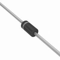
DIODE SCHOTTKY 50V 1A DO-41
Manufacturer
ON Semiconductor
Datasheet
1.MBR160RLG.pdf
(5 pages)
Specifications of MBR150RLG
Voltage - Forward (vf) (max) @ If
750mV @ 1A
Voltage - Dc Reverse (vr) (max)
50V
Current - Average Rectified (io)
1A
Current - Reverse Leakage @ Vr
500µA @ 50V
Diode Type
Schottky
Speed
Fast Recovery =< 500ns, > 200mA (Io)
Mounting Type
Through Hole
Package / Case
DO-204AL, DO-41, Axial
Product
Schottky Diodes
Peak Reverse Voltage
50 V
Forward Continuous Current
1 A @ Ta=55C
Max Surge Current
25 A
Configuration
Single
Forward Voltage Drop
1 V @ 3 A
Maximum Reverse Leakage Current
500 uA
Operating Temperature Range
- 65 C to + 150 C
Mounting Style
Through Hole
Lead Free Status / RoHS Status
Lead free / RoHS Compliant
Reverse Recovery Time (trr)
-
Capacitance @ Vr, F
-
Lead Free Status / Rohs Status
Lead free / RoHS Compliant
Other names
MBR150RLGOSTR
Available stocks
Company
Part Number
Manufacturer
Quantity
Price
Company:

Part Number:
MBR150RLG
Manufacturer:
ON
Quantity:
35 000


NOTE 1. — MOUNTING DATA:
(R
guideline values for preliminary engineering or in case the
tie point temperature cannot be measured.
Data shown for thermal resistance junction−to−ambient
qJA)
Mounting
90
80
70
60
50
40
30
20
10
Method
0.07
0.05
0.03
0.02
0.01
1.0
0.7
0.5
0.3
0.2
0.1
for the mounting shown is to be used as a typical
0
1
2
3
0.1
Figure 5. Steady−State Thermal Resistance
Typical Values for R
1/8
0.2
1/4
BOTH LEADS TO HEATSINK,
1/8
52
67
—
L, LEAD LENGTH (INCHES)
Lead Length, L (in)
0.5
EQUAL LENGTH
MAXIMUM
3/8
1/4
65
80
1.0
1/2
qJA
1/2
72
87
50
in Still Air
2.0
TYPICAL
5/8
100
THERMAL CHARACTERISTICS
3/4
85
3/4
5.0
Figure 4. Thermal Response
MBR150, MBR160
°C/W
°C/W
°C/W
R
http://onsemi.com
7/8
qJA
10
t, TIME (ms)
1.0
20
3
.
200
100
80
70
60
50
40
30
20
0
50
T
R
A(A)
qS(A)
DT
DT
temperature r(t) = normalized value of transient thermal resistance
at time, t, from Figure 4, i.e.: r(t) = r(t
transient thermal resistance at time, t
NOTE 2. — THERMAL CIRCUIT MODEL:
10
(For heat conduction through the leads)
JL
JL
t
T
Z
p
100
L(A)
qJL(t)
= P
= the increase in junction temperature above the lead
pk
R
20
Figure 6. Typical Capacitance
qL(A)
= Z
• R
t
1
200
V
qJL
P
qJL
R
pk
30
T
, REVERSE VOLTAGE (VOLTS)
C(A)
• r(t)
[D + (1 − D) • r(t
R
qJ(A)
40
T
P
500
J
pk
TIME
50
P
R
)
D
1
q J(K
1
1 k
1
+ t
DUTY CYCLE, D = t
PEAK POWER, P
of an equivalent square
power pulse.
+ t
60
+ t
p
p
) + r(t
p
T
) = normalized value of
.
C(K)
T
f = 1 MHz
70
2 k
p
J
R
) − r(t
= 25°C
qL(K)
80
1
)] where
T
L(K)
pk
, is peak
p
5 k
R
/t
90
T
1
qS(K)
A(K)
10 k
100
Related parts for MBR150RLG
Image
Part Number
Description
Manufacturer
Datasheet
Request
R

Part Number:
Description:
DIODE SCHOTTKY 1A 50V DO-41
Manufacturer:
ON Semiconductor
Datasheet:
Part Number:
Description:
ON Semiconductor [VOLTAGE REGULATOR]
Manufacturer:
ON Semiconductor
Datasheet:
Part Number:
Description:
357-036-542-201 CARDEDGE 36POS DL .156 BLK LOPRO
Manufacturer:
ON Semiconductor
Datasheet:
Part Number:
Description:
357-036-542-201 CARDEDGE 36POS DL .156 BLK LOPRO
Manufacturer:
ON Semiconductor
Datasheet:
Part Number:
Description:
357-036-542-201 CARDEDGE 36POS DL .156 BLK LOPRO
Manufacturer:
ON Semiconductor
Datasheet:
Part Number:
Description:
357-036-542-201 CARDEDGE 36POS DL .156 BLK LOPRO
Manufacturer:
ON Semiconductor
Datasheet:
Part Number:
Description:
357-036-542-201 CARDEDGE 36POS DL .156 BLK LOPRO
Manufacturer:
ON Semiconductor
Datasheet:
Part Number:
Description:
357-036-542-201 CARDEDGE 36POS DL .156 BLK LOPRO
Manufacturer:
ON Semiconductor
Datasheet:
Part Number:
Description:
357-036-542-201 CARDEDGE 36POS DL .156 BLK LOPRO
Manufacturer:
ON Semiconductor
Datasheet:
Part Number:
Description:
357-036-542-201 CARDEDGE 36POS DL .156 BLK LOPRO
Manufacturer:
ON Semiconductor
Datasheet:
Part Number:
Description:
357-036-542-201 CARDEDGE 36POS DL .156 BLK LOPRO
Manufacturer:
ON Semiconductor
Datasheet:
Part Number:
Description:
357-036-542-201 CARDEDGE 36POS DL .156 BLK LOPRO
Manufacturer:
ON Semiconductor
Datasheet: