8ETL06FPPBF Vishay, 8ETL06FPPBF Datasheet - Page 5
8ETL06FPPBF
Manufacturer Part Number
8ETL06FPPBF
Description
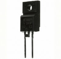
DIODE HYPERFAST 600V 8A TO220FP
Manufacturer
Vishay
Series
FRED Pt™r
Specifications of 8ETL06FPPBF
Diode Type
Standard
Voltage - Forward (vf) (max) @ If
1.05V @ 8A
Voltage - Dc Reverse (vr) (max)
600V
Current - Average Rectified (io)
8A
Current - Reverse Leakage @ Vr
5µA @ 600V
Speed
Fast Recovery =< 500ns, > 200mA (Io)
Reverse Recovery Time (trr)
250ns
Mounting Type
Through Hole
Package / Case
TO-220-2 Full Pack Fused Center, ITO-220AC
Product
Ultra Fast Recovery Rectifier
Configuration
Single
Reverse Voltage
600 V
Forward Voltage Drop
1.05 V
Recovery Time
250 ns
Forward Continuous Current
8 A
Max Surge Current
175 A
Reverse Current Ir
5 uA
Mounting Style
Through Hole
Maximum Operating Temperature
+ 175 C
Minimum Operating Temperature
- 65 C
Repetitive Reverse Voltage Vrrm Max
600V
Forward Current If(av)
8A
Forward Voltage Vf Max
1.05V
Reverse Recovery Time Trr Max
170ns
Lead Free Status / RoHS Status
Lead free / RoHS Compliant
Capacitance @ Vr, F
-
Lead Free Status / RoHS Status
Lead free / RoHS Compliant, Lead free / RoHS Compliant
Other names
*8ETL06FPPBF
VS-8ETL06FPPBF
VS-8ETL06FPPBF
VS8ETL06FPPBF
VS8ETL06FPPBF
VS-8ETL06FPPBF
VS-8ETL06FPPBF
VS8ETL06FPPBF
VS8ETL06FPPBF


Document Number: 94028
Revision: 24-Nov-08
450
400
350
300
250
200
150
100
50
0
Fig. 9 - Typical Reverse Recovery Time vs. dI
100
I
I
F
F
= 16 A
= 8 A
Discontinuous Mode PFC, 8 A FRED Pt
dI
(1) dI
(2) I
(3) t
0
Ultralow V
F
/dt (A/µs)
V
T
T
from zero crossing point of negative
going I
through 0.75 I
extrapolated to zero current.
through zero crossing
J
J
RRM
rr
R
I
F
F
= 125 °C
= 25 °C
- reverse recovery time measured
= 390 V
/dt - rate of change of current
- peak reverse recovery current
F
For technical questions, contact: diodes-tech@vishay.com
to point where a line passing
Fig. 12 - Reverse Recovery Waveform and Definitions
Fig. 11 - Reverse Recovery Parameter Test Circuit
RRM
F
Hyperfast Rectifier for
and 0.50 I
(1)
adjust
dI
F
/dt
dI
1000
F
F
/dt
RRM
/dt
L = 70 µH
G
t
a
(2)
V
(3)
R
= 200 V
I
RRM
t
0.01 Ω
D
rr
S
(4) Q
(5) dI
IRFP250
and I
current during t
rr
(rec)M
0.75 I
- area under curve defined by t
RRM
t
D.U.T.
b
/dt - peak rate of change of
8ETL06PbF, 8ETL06FPPbF
RRM
5000
4500
4000
3500
3000
2500
2000
1500
1000
TM
500
dI
0.5 I
Q
(rec)M
100
rr
Q
=
RRM
b
Vishay High Power Products
rr
/dt
Fig. 10 - Typical Stored Charge vs. dI
portion of t
I
I
t
F
F
(4)
rr
= 16 A
= 8 A
x I
(5)
2
RRM
rr
dI
rr
F
/dt (A/µs)
V
T
T
R
J
J
= 125 °C
= 25 °C
= 390 V
www.vishay.com
F
/dt
1000
5
Related parts for 8ETL06FPPBF
Image
Part Number
Description
Manufacturer
Datasheet
Request
R

Part Number:
Description:
DIODE HYPERFAST 600V 8A TO-220AC
Manufacturer:
Vishay
Datasheet:

Part Number:
Description:
DIODE HYPERFAST 600V 8A TO262
Manufacturer:
Vishay
Datasheet:

Part Number:
Description:
DIODE HYPERFAST 600V 8A TO-262
Manufacturer:
Vishay
Datasheet:

Part Number:
Description:
Ultra-low VF Hyperfast Rectifier for Discontinuous Mode PFC
Manufacturer:
IRF [International Rectifier]
Datasheet:

Part Number:
Description:
357-036-542-201 CARDEDGE 36POS DL .156 BLK LOPRO
Manufacturer:
Vishay
Datasheet:
Part Number:
Description:
357-036-542-201 CARDEDGE 36POS DL .156 BLK LOPRO
Manufacturer:
Vishay
Datasheet:
Part Number:
Description:
357-036-542-201 CARDEDGE 36POS DL .156 BLK LOPRO
Manufacturer:
Vishay
Datasheet:
Part Number:
Description:
357-036-542-201 CARDEDGE 36POS DL .156 BLK LOPRO
Manufacturer:
Vishay
Datasheet:
Part Number:
Description:
357-036-542-201 CARDEDGE 36POS DL .156 BLK LOPRO
Manufacturer:
Vishay
Datasheet:
Part Number:
Description:
357-036-542-201 CARDEDGE 36POS DL .156 BLK LOPRO
Manufacturer:
Vishay
Datasheet:
Part Number:
Description:
357-036-542-201 CARDEDGE 36POS DL .156 BLK LOPRO
Manufacturer:
Vishay
Datasheet:
Part Number:
Description:
357-036-542-201 CARDEDGE 36POS DL .156 BLK LOPRO
Manufacturer:
Vishay
Datasheet:
Part Number:
Description:
357-036-542-201 CARDEDGE 36POS DL .156 BLK LOPRO
Manufacturer:
Vishay
Datasheet:
Part Number:
Description:
357-036-542-201 CARDEDGE 36POS DL .156 BLK LOPRO
Manufacturer:
Vishay
Datasheet:
Part Number:
Description:
357-036-542-201 CARDEDGE 36POS DL .156 BLK LOPRO
Manufacturer:
Vishay
Datasheet: