HS13X-RO NKK Switches, HS13X-RO Datasheet - Page 5
HS13X-RO
Manufacturer Part Number
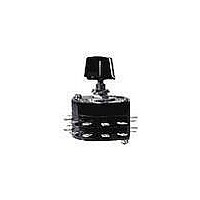
HS13X-RO
Description
2 POS, 6AMP 125VAC, BRASS SHAFT AND BUSHING
Manufacturer
NKK Switches
Type
Standard Size Rotariesr
Datasheet
1.AT432.pdf
(5 pages)
Specifications of HS13X-RO
Total # Of Positions
2
Pole Throw Configuration
SP
Actuator Style
Shaft
Actuator Material
Brass
Current Rating (max)
6A
Illumination Type
Not Required
Ac Voltage Rating (max)
250VVAC
Dc Voltage Rating (max)
30VVDC
Mechanical Life
15000
Contact Material
Phosphor Bronze
Product Height (mm)
40mm
Operating Temp Range
-10C to 70C
Mounting Style
Panel
Terminal Type
Screw
Number Of Positions
2
Number Of Poles Per Deck
1
Number Of Decks
1
Index Angle
45 deg
Contact Style
Non Shorting
Mounting Type
Panel
Dielectric Strength
1500 VoltsAC
Voltage Rating
125 VoltsAC, 250 VoltsAC, 30 VoltsDC
Current Rating
6 Amps, 3 Amps, 5 Amps
Actuator
Shaft, Round
Contact Rating
6 Amps at 125 VoltsAC, 3 Amps at 250 VoltsAC, 5 Amps at 30 VoltsDC
Termination Style
Solder Lug
Voltage Rating Ac
125 Volts, 250 Volts
Voltage Rating Dc
30 Volts
Lead Free Status / Rohs Status
Compliant


G
Series HS TS PS
G50
D Flat Shaft
For use with
AT431 and AT432
AT431
Large Knob
Phenolic Resin
Black only
with white
indicator
line
For HS16, TS, & PS Models
The HS16, TS, and PS switches are supplied with the stopper plate set for the
maximum number of positions allowed for that model. Prior to installation,
the desired stopper setting should be made:
1.
2.
3.
4.
Standard Hardware Supplied with HS, TS, and PS:
Be sure the shaft is turned counterclockwise to the extreme left. If the
shaft is not turned counterclockwise to the extreme left, proper setting
cannot be achieved.
Loosen the nut far enough to allow raising the stopper plate for resetting.
Insert the stopper in the numbered hole for the desired stopper setting.
Satisfactory switch functioning cannot be assured if the stopper plate is
not properly positioned.
Tighten the nut firmly against the stopped plate.
AT526 Hex Mounting Nut (quantity 3)
AT518 Locking Ring (quantity 1)
AT520 Split Lockwasher (quantity 1)
Use of mounting supports on PS is optional; screws are not provided.
(9.0)
.354
(5.5)
.217
(24.0)
.945
(29.0)
1.142
(28.0)
M2.3 x 0.4 x 8.0
1.102
.236
(6.0) Dia
(30.0) Dia
1.181
(4.4)
.173
(24.0)
.945
Dim A
OPTIONAL KNOBS FOR D FLAT SHAFTS
(19.5)
Dim B
.768
2.244
(57.0)
Dimension A
For TS
For HS (10.0)
or PS
AT432
Small Knob
Phenolic Resin
Black only
with white
indicator
line
.354
(9.0)
STOPPER SETTING
www.nkk.com
(5.5)
.217
(13.0)
.394
.512
SHAFT TYPES
Dimension B
For TS
For HS (15.0)
or PS
(21.0)
.827
(21.0)
.827
(15.6)
.591
.614
(20.0)
.787
M2.3 x 0.4 x 8.0
(21.0)
.827
(25.0) Dia
.984
Knurled Shaft
Not for use with
AT431 or AT432
(15.6)
.614
(41.0)
1.614
Knob Orientation
The rotary
knobs used
on the D-flat
shafts can
be oriented
on the switch
to suit the
customer’s
particular
front panel
needs simply
by sliding the
knob over
the square
adaptor at
the preferred
orientation.
Standard Size Rotaries
.236
(6.0) Dia
Set Screw
Shaft
Assembly Screw
Adaptor
(20.0)
.787
AT526
AT518
AT520
AT526
AT526
Related parts for HS13X-RO
Image
Part Number
Description
Manufacturer
Datasheet
Request
R

Part Number:
Description:
Rotary Switches 2 POS ROTARY D SHAFT
Manufacturer:
NKK Switches
Datasheet:

Part Number:
Description:
SW ROTARY SP 6A NON SHORT 2POS
Manufacturer:
NKK Switches
Datasheet:

Part Number:
Description:
SWITCH ROTARY 2POS 6A NONSHORT
Manufacturer:
NKK Switches
Datasheet:

Part Number:
Description:
Rocker Switches & Paddle Switches High In-rush Rated Rocker Switch
Manufacturer:
NKK Switches
Datasheet:
Part Number:
Description:
Rocker Switches & Paddle Switches High In-rush Rated Rocker Switch
Manufacturer:
NKK Switches
Datasheet:
Part Number:
Description:
Rocker Switches & Paddle Switches High In-rush Rated Rocker Switch
Manufacturer:
NKK Switches
Datasheet:
Part Number:
Description:
Rocker Switches & Paddle Switches High In-rush Rated Rocker Switch
Manufacturer:
NKK Switches
Datasheet:

Part Number:
Description:
Pushbutton Switches SPST ON(OFF) 15/32'
Manufacturer:
NKK Switches
Datasheet:

Part Number:
Description:
Pushbutton Switches SPST OFF(ON) 15/32'
Manufacturer:
NKK Switches
Datasheet:

Part Number:
Description:
Pushbutton Switches ON(OFF) NORM CLSD 3A RED PLNGR LUG 15/32
Manufacturer:
NKK Switches
Datasheet:

Part Number:
Description:
Pushbutton Switches SPDT ON-(ON)
Manufacturer:
NKK Switches
Datasheet:

Part Number:
Description:
Pushbutton Switches ON-(ON) RND BUSH MNT RED LED RED/RED CAP
Manufacturer:
NKK Switches
Datasheet:
Part Number:
Description:
Pushbutton Switches SPST ON-(OFF) STRT
Manufacturer:
NKK Switches
Datasheet:
Part Number:
Description:
Pushbutton Switches OFF(ON) NORM OPEN 3A RED CAP LUG 15/32
Manufacturer:
NKK Switches
Datasheet:
Part Number:
Description:
Pushbutton Switches ILLUM PUSHBUTTON SPDT
Manufacturer:
NKK Switches
Datasheet: