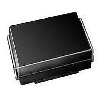
SS2H10-E3/5BT Vishay, SS2H10-E3/5BT Datasheet - Page 3

SS2H10-E3/5BT
Manufacturer Part Number
SS2H10-E3/5BT
Description
DIODE SCHOTTKY 2A 100V SMB
Manufacturer
Vishay
Datasheet
1.SS2H10-E35BT.pdf
(4 pages)
Specifications of SS2H10-E3/5BT
Voltage - Forward (vf) (max) @ If
790mV @ 2A
Voltage - Dc Reverse (vr) (max)
100V
Current - Average Rectified (io)
2A
Current - Reverse Leakage @ Vr
10µA @ 100V
Diode Type
Schottky
Speed
Fast Recovery =< 500ns, > 200mA (Io)
Mounting Type
Surface Mount
Package / Case
DO-214AA, SMB
Product
Schottky Diodes
Peak Reverse Voltage
100 V
Forward Continuous Current
2 A
Max Surge Current
75 A
Configuration
Single
Forward Voltage Drop
0.79 V
Maximum Reverse Leakage Current
10 uA
Operating Temperature Range
- 65 C to + 175 C
Mounting Style
SMD/SMT
Lead Free Status / RoHS Status
Lead free / RoHS Compliant
Reverse Recovery Time (trr)
-
Capacitance @ Vr, F
-
Lead Free Status / RoHS Status
Lead free / RoHS Compliant, Lead free / RoHS Compliant
Available stocks
Company
Part Number
Manufacturer
Quantity
Price
Part Number:
SS2H10-E3/5BT
Manufacturer:
VISHAY/威世
Quantity:
20 000
PACKAGE OUTLINE DIMENSIONS in inches (millimeters)
Document Number: 88750
Revision: 19-May-08
10 000
0.001
1000
0.01
0.01
100
100
Figure 3. Typical Instanteous Forward Characteristics
0.1
0.1
10
10
1
1
10
0
Figure 4. Typical Reverse Characteristics
Percent of Rated Peak Reverse Voltage (%)
20
0.2
Instantaneous Forward Voltage (V)
T
30
J
= 150 °C
0.4
0.086 (2.20)
0.077 (1.95)
0.096 (2.44)
0.084 (2.13)
0.060 (1.52)
0.030 (0.76)
40
T
T
T
J
0.6
J
J
= 175 °C
T
= 150 °C
50
= 125 °C
PDD-Americas@vishay.com, PDD-Asia@vishay.com, PDD-Europe@vishay.com
J
T
= 175 °C
For technical questions within your region, please contact one of the following:
J
= 25 °C
T
T
J
60
0.8
J
= 125 °C
= 25 °C
DO-214AA (SMB)
70
1.0
0.180 (4.57)
0.160 (4.06)
0.220 (5.59)
0.205 (5.21)
Cathode Band
80
1.2
0.008 (0.2)
90
0 (0)
100
1.4
0.155 (3.94)
0.130 (3.30)
0.012 (0.305)
0.006 (0.152)
0.060 (1.52) MIN.
0.086 (2.18) MIN.
Figure 6. Typical Transient Thermal Impedance Per Leg
1000
100
100
10
10
1
0.01
0.1
Vishay General Semiconductor
Figure 5. Typical Junction Capacitance
Mounting Pad Layout
0.220 REF.
0.1
t - Pulse Duration (s)
Reverse Voltage (V)
1
0.085 (2.159) MAX.
SS2H9 & SS2H10
1
10
10
www.vishay.com
100
100
3


