UHF5JT-E3/4W Vishay, UHF5JT-E3/4W Datasheet
UHF5JT-E3/4W
Specifications of UHF5JT-E3/4W


Related parts for UHF5JT-E3/4W


UHF5JT-E3/4W Summary of contents
Page 1
... Mounting Torque: 10 in-lbs maximum SYMBOL V RRM I F(AV) I FSM STG = 25 °C unless otherwise noted) C TEST CONDITIONS SYMBOL ° 125 °C A UH5JT & UH5JT Vishay General Semiconductor UH5JT UHF5JT 600 8 60 1500 - 175 TYP. MAX. 1.71 - 2.3 3.0 1.13 - 1.39 1.8 www.vishay.com UNIT °C UNIT V 1 ...
Page 2
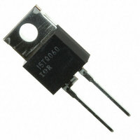
... Pulse test: 300 µs pulse width duty cycle (2) Pulse test: Pulse width ≤ THERMAL CHARACTERISTICS (T PARAMETER Typical thermal resistance from junction to case ORDERING INFORMATION (Example) PACKAGE PREFERRED P/N TO-220AC UH5JT-E3/4W ITO-220AC UHF5JT-E3/4W RATINGS AND CHARACTERISTICS CURVES ( °C unless otherwise noted Resistive or Inductive Load 5 4 UHF5JT 3 ...
Page 3
... CASE PIN 2 0.105 (2.67) 0.037 (0.94) 0.095 (2.41) 0.027 (0.68) 0.205 (5.20) 0.195 (4.95) Document Number: 88999 For technical questions within your region, please contact one of the following: Revision: 13-May-08 PDD-Americas@vishay.com, PDD-Asia@vishay.com, PDD-Europe@vishay.com 100 10 2.4 2.7 3 100 0.185 (4.70) 0.175 (4.44) ...
Page 4
... Vishay product could result in personal injury or death. Customers using or selling Vishay products not expressly indicated for use in such applications their own risk and agree to fully indemnify and hold Vishay and its distributors harmless from and against any and all claims, liabilities, expenses and damages arising or resulting in connection with such use or sale, including attorneys fees, even if such claim alleges that Vishay or its distributor was negligent regarding the design or manufacture of the part ...