G7S-4A2B DC24 Omron, G7S-4A2B DC24 Datasheet - Page 5
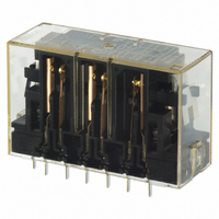
G7S-4A2B DC24
Manufacturer Part Number
G7S-4A2B DC24
Description
Contact OSTI For Purchase
Manufacturer
Omron
Series
G7Sr
Datasheets
1.G7SA-3A1B-DC24.pdf
(8 pages)
2.G7S-4A2B_DC24.pdf
(6 pages)
3.P7S-14F-END-DC24.pdf
(6 pages)
Specifications of G7S-4A2B DC24
Relay Type
Safety
Mounting Type
Socket
Contact Form
6PST (4 Form A, 2 Form B)
Contact Rating (current)
6A
Switching Voltage
250VAC, 24VDC - Max
Coil Type
Standard
Coil Current
30mA
Coil Voltage
24VDC
Turn On Voltage (max)
19.2 VDC
Turn Off Voltage (min)
2.4 VDC
Termination Style
Socketable
Circuit
6PST (4 Form A, 2 Form B)
Contact Rating @ Voltage
6A @ 24VDC
Control On Voltage (max)
19.2 VDC
Control Off Voltage (min)
2.4 VDC
Contact Current Rating
30 mA at 24 V
Coil Power Rating
0.8 W
Coil Voltage Vdc Nom
24V
Coil Resistance
800ohm
Contact Configuration
4PST-NO / DPST-NC
Relay Mounting
Plug In
Coil Power Vdc
0.8W
Carry Current
6A
Current Rating (max)
6 A
Contact Current Max
6A
Contact Voltage Ac Nom
240V
Contact Voltage Dc Nom
24V
No. Of Poles
6
Rohs Compliant
Yes
Lead Free Status / RoHS Status
Lead free / RoHS Compliant
Lead Free Status / RoHS Status
Lead free / RoHS Compliant
Other names
G7S-4A2B-DC24
G7S-4A2B-DC24
G7S4A2BDC24
Z2362
G7S-4A2B-DC24
G7S4A2BDC24
Z2362


Certified Standards
Safety Precautions
Refer to the “Precautions for All Relays” and “Precautions for All Relays with Forcibly Guided Contacts”.
Wiring
Cleaning
The G7S is not of enclosed construction. Therefore, do not wash the
G7S with water or detergent.
• EN Standards, VDE Certified
• UL standard UL508 Industrial Control Devices
• CSA standard CSA C22.2 No. 14 Industrial Control Devices
• Use one of the following wires to connect to the P7S-14F-END.
• Tighten each screw of the P7S-14F-END to a torque of 0.78
• Refer to the internal connections diagram of the G9S Safety Relay
• Wire the terminals correctly with no mistakes in coil polarity,
EN61810-1 (Electromechanical non-specified time all-or-nothing
relays)
EN50205 (Relays with forcibly guided (linked) contacts)
to 0.98 N·m.
Unit for an application example of the G7S.
otherwise the G7S will not operate.
Stranded wire: 0.75 to 1.5 mm
Solid wire:
Precautions for Correct Use
1.0 to 1.5 mm
2
2
Forcibly Guided Contacts
If an NO contact becomes welded, all NC contacts will maintain a
minimum distance of 0.5 mm when the coil is not energized. Likewise
if an NC contact becomes welded, all NO contacts will maintain a
minimum distance of 0.5 mm when the coil is energized.
(from EN50205)
G7S
5
Related parts for G7S-4A2B DC24
Image
Part Number
Description
Manufacturer
Datasheet
Request
R


Part Number:
Description:
24M2523
Manufacturer:
Omron
Datasheet:

Part Number:
Description:
G6S-2GLow Signal Relay
Manufacturer:
Omron Corporation
Datasheet:
Part Number:
Description:
Compact, Low-cost, SSR Switching 5 to 20 A
Manufacturer:
Omron Corporation
Datasheet:
Part Number:
Description:
Manufacturer:
Omron Corporation
Datasheet:
Part Number:
Description:
Manufacturer:
Omron Corporation
Datasheet:
Part Number:
Description:
Manufacturer:
Omron Corporation
Datasheet:
Part Number:
Description:
Manufacturer:
Omron Corporation
Datasheet:
Part Number:
Description:
Manufacturer:
Omron Corporation
Datasheet:
Part Number:
Description:
Manufacturer:
Omron Corporation
Datasheet: