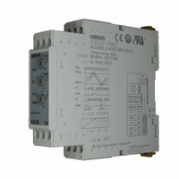
K8AB-PW2 Omron, K8AB-PW2 Datasheet - Page 9

K8AB-PW2
Manufacturer Part Number
K8AB-PW2
Description
3-phs Voltage Ry. 380-480VAC
Manufacturer
Omron
Series
K8ABr
Datasheets
1.K8AB-TH12S_ACDC24.pdf
(8 pages)
2.K8AB-PW2.pdf
(10 pages)
3.K8AB-VS3_100115VAC.pdf
(8 pages)
Specifications of K8AB-PW2
Contact Form
SPDT
Coil Voltage
200 VAC to 500 VAC
Contact Rating
6 A at 250 VAC
Mounting Style
DIN Rail
Lead Free Status / RoHS Status
Lead free / RoHS Compliant
Lead Free Status / RoHS Status
Lead free / RoHS Compliant
Other names
K8A-BPW2
K8ABPW2
Z2807
K8ABPW2
Z2807
Example: For monitoring mode set to three-phase three-wire
Note: K8AB-PW@ output relays are normally operative.
Connection Diagram
L1
L2
L3
Q
3φ,
200 VAC
Alarm indicator
Checking Operation
Overvoltage
Undervoltage
Input voltage
Relay output
Gradually increase the input from 80% of the setting.
The input value will equal the operating value when the
input exceeds the setting and the alarm indicator starts
flashing. Operation can be checked by the relay output that
will start after the operating time has passed.
Gradually decrease the input from 120% of the setting and
check the operation using the same method as for
overvoltage.
monitoring, a rated voltage of 200 V, and an operating time
of 5 s.
Set value
Questions and Answers
ALL DIMENSIONS SHOWN ARE IN MILLIMETERS.
To convert millimeters into inches, multiply by 0.03937. To convert grams into ounces, multiply by 0.03527.
Three-phase
variable autotransformer
In the interest of product improvement, specifications are subject to change without notice.
0 to 150 V
V2 V3
V1
Flashing
5 s
Lit
L1
L2
L3
Overvoltage
Undervoltage
Connection Diagram
L1
L2
L3
Q
Q
Q
3φ,
200 VAC
X
How to Measure the Operating Time
Overvoltage
Undervoltage
Operating Time
Operating Adjustment Knobs
Use a screwdriver to turn the knobs. There is a stopper to
prevent the knob from turning any further once it has been
turned completely to the left or right. Do not force the knob
past these limits.
Overvoltage Detection When Only One Phase Exceeds
the Overvoltage Threshold
The K8AB monitors each of the three-phase voltages. This
means an overvoltage is detected if even only one phase
exceeds the threshold value. The same applies to
undervoltages.
Change the input suddenly from 0% to 120% of the set
value and measure the time until the Unit operates.
Change the input suddenly from 120% to 0% of the set
value and measure the time until the Unit operates.
Adjust the slide resistor so that the voltage applied to the
K8AB terminals is 120% of the overvoltage set value or
80% of the undervoltage set value when the auxiliary relay
operates in a test circuit. Close the switch and use the
cycle counter to measure the operating time.
X/a
Cycle counter
±
C 200 V
R1: Slide resistor
R2: 100 Ω 400 W
R1
R2
200 Ω 200 W
X/b
K8AB-PW
V2 V3
V1
L1
L2
L3
9


