A165E-LS-24D-02 Omron, A165E-LS-24D-02 Datasheet - Page 7
A165E-LS-24D-02
Manufacturer Part Number
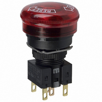
A165E-LS-24D-02
Description
E-stop,lighted,2NC,30diameter
Manufacturer
Omron
Series
A16r
Type
Emergency Stop, Illuminatedr
Specifications of A165E-LS-24D-02
Circuit
DPST-NC
Switch Function
On-Off
Contact Rating @ Voltage
5A @ 125VAC
Actuator Type
Round Button
Illumination Type, Color
LED, Red
Illumination Voltage (nominal)
24 VDC
Mounting Type
Panel Mount
Termination Style
Solder, Quick Connect - .110" (2.8mm)
Illumination
Red
Control Type
Emergency Stop
Contact Form
DPST - NC
Contact Rating
5 Amps at 125 VoltsAC
Illuminated
Y
Lens Color
Red
Lead Free Status / RoHS Status
Lead free / RoHS Compliant
Lead Free Status / RoHS Status
Lead free / RoHS Compliant
Other names
A165ELS24D02
Z1426
Z1426


Installation
A165-E
J MOUNTING THE PANEL
After installing the Switch, snap in the Socket Unit from the back
of the panel.
1. Installing the Switch
Attach rubber packing or the Yellow Plate onto the Switch from its
terminal side. Insert the Switch into the panel from the front.
Install the lock ring and mounting nut from the terminal side and
tighten.
Adjust the slits on the hole of rubber packing and Yellow Plate to
the protruding part of the unit.
Note: Rubber packing is not necessary when the Yellow Plate is
Tighten the nut to the torque of 0.29 to 0.49 N S m.
Case should be installed with its protruding part adjusted to the
slit of the panel hole.
Align the lock ring to the groove of the case so that the edge is
drawn to the panel side.
View 2
View 1
Lock hole
Rubber packing or yellow plate (sold separately)
used.
Cutout
Lock
Panel
Edge
Mounting nut
Lock ring
Mounting nut
Rubber packing
(attached to the prod-
uct) or yellow plate
(sold separately)
Lock ring
Panel
8
2. Mounting the Socket Unit
Snap on the Socket Unit to the Switch.
Make sure the Switch and the Socket Unit are in the proper
orientation. Align the thin indentations on the case with the white
pushbutton markings on the Socket Unit and press the parts
together.
3 Removing the Switch
Grip the part between the Switch holder of the case and the Switch
Unit using the A16Z-5080 Extractor, and pull to remove the Switch
Unit.
4. Installing the LED Lamp
When mounting the Lamp, make sure it is facing the direction
shown in the following diagram. Insert the Lamp while matching
the protruding part of the Lamp and the small guides on the outer
surface of the case.
Protruding part
Extractor
(A16Z-5080)
Related parts for A165E-LS-24D-02
Image
Part Number
Description
Manufacturer
Datasheet
Request
R

Part Number:
Description:
ESTOP OPERATOR
Manufacturer:
Omron
Datasheet:

Part Number:
Description:
E-stop,lighted,1NC,30diameter
Manufacturer:
Omron
Datasheet:

Part Number:
Description:
E-stop,non-lighted,30diameter
Manufacturer:
Omron
Datasheet:
Part Number:
Description:
ESTOP OPERATOR
Manufacturer:
Omron
Datasheet:
Part Number:
Description:
1 NC CONTACT
Manufacturer:
Omron
Datasheet:

Part Number:
Description:
2 NC CONTACTS
Manufacturer:
Omron
Datasheet:
Part Number:
Description:
2 NC CONTACTS
Manufacturer:
Omron
Datasheet:
Part Number:
Description:
ESTOP OPERATOR
Manufacturer:
Omron
Datasheet:
Part Number:
Description:
E-stop,lighted,1NC,40diameter
Manufacturer:
Omron
Datasheet:
Part Number:
Description:
E-stop,lighted,2NC,40diameter
Manufacturer:
Omron
Datasheet:

Part Number:
Description:
SWITCH PB SQUARE MOM SPDT GREEN
Manufacturer:
Omron
Datasheet:
Part Number:
Description:
SWITCH PB SQUARE MOM SPDT WHITE
Manufacturer:
Omron
Datasheet:
Part Number:
Description:
SWITCH PB SQUARE MOM SPDT YELLOW
Manufacturer:
Omron
Datasheet:
Part Number:
Description:
SWITCH PB RECTANG MOM SPDT BLUE
Manufacturer:
Omron
Datasheet:
Part Number:
Description:
SWITCH PB RECTANG MOM SPDT YEL
Manufacturer:
Omron
Datasheet: