A165E-M-03U Omron, A165E-M-03U Datasheet - Page 14
A165E-M-03U
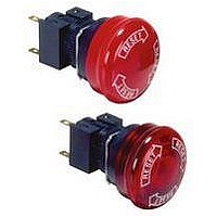
Manufacturer Part Number
A165E-M-03U
Description
E-stop,non-lighted,40diameter
Manufacturer
Omron
Specifications of A165E-M-03U
Contact Configuration
3PST-NC
Switch Operation
Pushlock Turn Reset
Contact Voltage Ac Nom
250V
Contact Voltage Dc Nom
30V
Contact Current Max
5A
Actuator Style
Round
Control Type
Emergency Stop
Contact Form
3PST - NC
Contact Rating
10 mAmps
Illuminated
N
Lead Free Status / RoHS Status
Lead free / RoHS Compliant
Lead Free Status / RoHS Status
Lead free / RoHS Compliant


Mounting Precautions
Wiring
Soldering
Typical Soldering Example
• Perform wiring so that the lead wires will not be caught on other objects
• With miniature Switches, the gap between the terminals is very
• There are two methods for soldering the Switch: hand soldering and
Hand soldering
Automatic
soldering
• Do not use soldering flux that contains chlorine. Doing so may
as this will cause stress on the Switch terminals. Wire the Switch so
that there is slack in the lead wires and fix lead wires at intermediate
points. If the panel to which the Switch is mounted needs to be opened
and closed for maintenance purposes, perform wiring so that the
opening and closing of the panel will not interfere with the wiring.
narrow. Use protective or heat-absorbing tubes to prevent burning
of the wire sheath or shorting.
automatic soldering. In addition, automatic soldering itself can be
divided into two types : dip soldering and reflow soldering. Use the
soldering method appropriate for the mounting method.
result in metal corrosion.
Method
Dip
soldering
Reflow
soldering
http://www.ia.omron.com/
Soldering iron
Jet soldering bath
Dip soldering bath
Infrared reflow (IR)
soldering bath
Vapor-phase (VPS)
reflow soldering bath
Soldering device
Protective tube
Small quantities
Different materials
Lead wire terminals
Large quantities of
discrete terminals
Large quantities
of miniature SMD
terminals
Application
Technical Guide for Pushbutton Switches
Termina
• Perform hand soldering using the appropriate soldering iron.
• With the exception of PCB-mounting Switches, when performing
• Leave a gap of at least 1 mm between the soldered parts and the
• When applying flux using a brush, use a sponge soaked in flux as
hand soldering, hold the Switch so that the terminals point
downwards so that flux does not get inside the Switch.
surface of the case so that flux does not get inside the Switch.
shown below. Do not apply more than is necessary. Also, apply the
flux with the PCB inclined at an angle of less than 80° so that flux
does not flow onto the mounting surface of the Switch.
l
Lead wire
(c)Copyright OMRON Corporation 2007 All Rights Reserved.
Large-capacity
soldering iron
Sponge
soaked in flux
Flux
Lead wire
Terminal
Solder
Case
Brush
Small-capacity
soldering iron
used for a long
time
Brush
80 °
max.
1 mm min.
Perform soldering for
between 3 to 5 s with
a suitable soldering iron.
C-5
Related parts for A165E-M-03U
Image
Part Number
Description
Manufacturer
Datasheet
Request
R

Part Number:
Description:
SWITCH, EMERGENCY STOP, DPST-NC, 250VAC
Manufacturer:
Omron
Datasheet:

Part Number:
Description:
ESTOP OPERATOR
Manufacturer:
Omron
Datasheet:
Part Number:
Description:
E-stop,non-lighted,1NC,40diamt
Manufacturer:
Omron
Datasheet:
Part Number:
Description:
ESTOP OPERATOR
Manufacturer:
Omron
Datasheet:
Part Number:
Description:
1 NC CONTACT
Manufacturer:
Omron
Datasheet:

Part Number:
Description:
2 NC CONTACTS
Manufacturer:
Omron
Datasheet:
Part Number:
Description:
2 NC CONTACTS
Manufacturer:
Omron
Datasheet:
Part Number:
Description:
ESTOP OPERATOR
Manufacturer:
Omron
Datasheet:
Part Number:
Description:
E-stop,lighted,1NC,40diameter
Manufacturer:
Omron
Datasheet:
Part Number:
Description:
E-stop,lighted,2NC,40diameter
Manufacturer:
Omron
Datasheet:

Part Number:
Description:
SWITCH PB SQUARE MOM SPDT GREEN
Manufacturer:
Omron
Datasheet:
Part Number:
Description:
SWITCH PB SQUARE MOM SPDT WHITE
Manufacturer:
Omron
Datasheet:
Part Number:
Description:
SWITCH PB SQUARE MOM SPDT YELLOW
Manufacturer:
Omron
Datasheet:
Part Number:
Description:
SWITCH PB RECTANG MOM SPDT BLUE
Manufacturer:
Omron
Datasheet:
Part Number:
Description:
SWITCH PB RECTANG MOM SPDT YEL
Manufacturer:
Omron
Datasheet: